| Search | Login/Register
   Home » Melquiades Amplifier » Planning my DSET (187 posts, 10 pages)
  Print Thread | 1st Post |  
Page 6 of 10 (187 items) Select Pages:  « First ... « 4 5 6 7 8 » ... Last »
04-05-2017 Post does not mapped to Knowledge Tree
anthony
Posts 335
Joined on 08-18-2014

Post #: 101
Post ID: 23103
Reply to: 23101
It is a good idea
 N-set wrote:
Very cool idea with a built in pneumatical (?) vibroisolation!
I run a small company offering pneumatic isolation platforms for audio. I attempted to
talk to various equipment manufacturers about building in such solutions into their products.
Unfortunately no interest in that. But great to see someone taking this idea seriously.

Cheers,
Jarek


Hi Jarek,

It was your thread on here that prompted me to think about incorporating the vibroisolation into the amplifer.  Although not seen, I have also designed in some ball bearing horizontal isolation that sits on top of the pneumatics.  Hopefully soon I will have the prototype for those parts machined and tested.

Regards,

Anthony
04-05-2017 Post does not mapped to Knowledge Tree
N-set
Gdansk, Poland
Posts 609
Joined on 01-07-2006

Post #: 102
Post ID: 23104
Reply to: 23103
I'm honoured
 anthony wrote:

Hi Jarek,

It was your thread on here that prompted me to think about incorporating the vibroisolation into the amplifer.  Although not seen, I have also designed in some ball bearing horizontal isolation that sits on top of the pneumatics.  Hopefully soon I will have the prototype for those parts machined and tested.

Regards,

Anthony


Haha! Really?  Which thread ? I think you confuse this forum with lencoheaven where I was documenting my fight with vibroisolation Smile
There was a guy asking me for a pneumatical diagram. Was that you?

Cheers,
jarek


Cheers,
Jarek
STACORE
04-05-2017 Post does not mapped to Knowledge Tree
Romy the Cat


Boston, MA
Posts 10,049
Joined on 05-27-2004

Post #: 103
Post ID: 23106
Reply to: 23098
Not Alzheimer’s, yet…
Anthony, I have an unexpected advice to you. Label all knobs, testing points, input and outputs. Everything sounds to you very logical and self-explanatory not but, so it was to me. In 12 years you will be looking at the thing and wondering where is the knob to adjust the DC at DHT stage and where the specific testing jack for a specific 6C33C bias is and how it differ from the testing jack for 6E5P plate. I am 48 and it is not that I am having Alzheimer’s, yet, but with touching it for years the thing like this run out of memory. So, ether label everything of make the test point and knobs map  and put the map in some kind of save place inside the amp. 


"I wish I could score everything for horns." - Richard Wagner. "Our writing equipment takes part in the forming of our thoughts." - Friedrich Nietzsche
04-05-2017 Post does not mapped to Knowledge Tree
N-set
Gdansk, Poland
Posts 609
Joined on 01-07-2006

Post #: 104
Post ID: 23107
Reply to: 23106
I second Romy,
 but would correct that this forgetting time can be shorter than 12 weeks in some human specimens (like me)


Cheers,
Jarek
STACORE
04-05-2017 Post does not mapped to Knowledge Tree
anthony
Posts 335
Joined on 08-18-2014

Post #: 105
Post ID: 23108
Reply to: 23104
Is this another N-Set?
 N-set wrote:
 anthony wrote:

Hi Jarek,

It was your thread on here that prompted me to think about incorporating the vibroisolation into the amplifer.  Although not seen, I have also designed in some ball bearing horizontal isolation that sits on top of the pneumatics.  Hopefully soon I will have the prototype for those parts machined and tested.

Regards,

Anthony


Haha! Really?  Which thread ? I think you confuse this forum with lencoheaven where I was documenting my fight with vibroisolation Smile
There was a guy asking me for a pneumatical diagram. Was that you?

Cheers,
jarek


http://goodsoundclub.com/Forums/ShowPost.aspx?PageIndex=4&postID=20385#20385

I've not seen the lencoheavan forum but that link above is 4 pages of you on this site.  For alzheimers I suggest 30 minutes of exercise a day and lots of crossword and other puzzles...haha...so easy to do.
04-05-2017 Post does not mapped to Knowledge Tree
anthony
Posts 335
Joined on 08-18-2014

Post #: 106
Post ID: 23109
Reply to: 23106
The failing memory
 Romy the Cat wrote:
Anthony, I have an unexpected advice to you. Label all knobs, testing points, input and outputs. Everything sounds to you very logical and self-explanatory not but, so it was to me. In 12 years you will be looking at the thing and wondering where is the knob to adjust the DC at DHT stage and where the specific testing jack for a specific 6C33C bias is and how it differ from the testing jack for 6E5P plate. I am 48 and it is not that I am having Alzheimer’s, yet, but with touching it for years the thing like this run out of memory. So, ether label everything of make the test point and knobs map  and put the map in some kind of save place inside the amp. 


Most definitely yes to the labels.  The analogue meters will have a mix of fullscale deflections (250mA, 50mA etc.) and therefore I have to make new 'labels' for their internals and on each of these labels will be the channel name (Upperbass, Midrange, Fundamentals etc.).  There is a local signwriter that I use from time to time and he will make up some nice decals to put on the steel panel above the knobs to identify the channel.  Similarly, the stepped attenuators will have not only the channel but the attenuation marked.

I half struggle to remember which is which now so in a years time I might have no clue at all. 
04-05-2017 Post does not mapped to Knowledge Tree
N-set
Gdansk, Poland
Posts 609
Joined on 01-07-2006

Post #: 107
Post ID: 23110
Reply to: 23108
Alzheimer!
Ah ok, these are just the results. I forgot about this post Big Smile


Cheers,
Jarek
STACORE
04-05-2017 Post does not mapped to Knowledge Tree
anthony
Posts 335
Joined on 08-18-2014

Post #: 108
Post ID: 23113
Reply to: 23102
Not too late
 oxric wrote:
Hi Anthony,

I am amazed by the work you have accomplished so far and love your stands and horns stacks.

Two comments though in term of overall esthetics although I realise that having spent so much time on this it may be too late to make changes.

I would not have the amplifier hidden behind the main pillar supporting the horns. It distracts from the beautiful lines of horns and support. In addition, I think, if only in theory, to completely isolate your amplifiers and power supplies from your horns and drivers, would be a good thing. I appreciate that you do reduce cable lengths by doing so but am inclined to think that by positioning your amplifiers along side walls, the benefits outweigh these other disadvantages.

Secondly, the bass cannons. Sadurni Acoustics does something very similar but I think this contraption with the several separate individual bass enclosures is an unecessary distraction from the horns and support. I would try to use a bass tower, maybe two modules of 4 drivers each, and still make provision for alignment of these drivers within its design.

Please ignore comments at leisure as your project is quite remarkable as it is.

rgds
Rakesh

Hi Rakesh,

I've talked about this stuff in the other thread on this site so maybe pop over there and leave your opinion on the bass array.  Thanks for you compliments by the way.

Regards,

Anthony
04-17-2017 Post does not mapped to Knowledge Tree
N-set
Gdansk, Poland
Posts 609
Joined on 01-07-2006

Post #: 109
Post ID: 23157
Reply to: 23108
Airborne
Anthony, I'm sure you realize that air springs and bearings can only isolate from the structure born vibrations. Placing the tubes so close to the speakers you give them a great chance to catch strong airborne vibrations. Or will they be shadowed by the horns? 

BTW What soft have you used for the visualizations? Cimatron?


Cheers,
Jarek
STACORE
04-17-2017 Post does not mapped to Knowledge Tree
Paul S
San Diego, California, USA
Posts 2,570
Joined on 10-12-2006

Post #: 110
Post ID: 23158
Reply to: 23157
EMF
Anthony, N-set makes a good point.  Also, based on the perspectives, how do you isolate the tubes from the transformers?


Best regards,
Paul S
04-17-2017 Post does not mapped to Knowledge Tree
anthony
Posts 335
Joined on 08-18-2014

Post #: 111
Post ID: 23159
Reply to: 23157
Low frequency vibration is not so easy to deal with
 N-set wrote:
Anthony, I'm sure you realize that air springs and bearings can only isolate from the structure born vibrations. Placing the tubes so close to the speakers you give them a great chance to catch strong airborne vibrations. Or will they be shadowed by the horns? 

BTW What soft have you used for the visualizations? Cimatron?


 Paul S wrote:
Anthony, N-set makes a good point.  Also, based on the perspectives, how do you isolate the tubes from the transformers?


Best regards,
Paul S


Where the amplifiers go in the room is sort of a damned if I do, damned if I don't kind of situation.  I don't want them sitting in a low pressure node and would prefer them in a low pressure null, but the position of these nodes and nulls vary according to frequency and proximity to room boundaries and I am unable to plan for them in advance.  So I have made the following plans to deal with the effect of vibration in the amplifiers:
  1. The power supply for each mono is in a completely separate chassis situated on the floor with footer that isolate from somewhere near 15Hz with the weight loading that they have on them.  The power transformers and chokes sit on non-ferrous aluminium platforms that float on appropriately loaded sorbothane bushings.  This maximises the distance from any steel that they can excite thus reducing the tendency to hum or buzz.  I have also lined all external steel surfaces of the PS chassis with a CLD system consisting of a 2mm thick vicoelastic damper and 1mm thick aluminium sheet.  This works very well and I will use the same CLD system in the amplifier.  

  2. The amplifier sits on a pneumatic and ball bearing isolation system designed to provide effective isolation from about 4Hz. This should be enough to isolate the amplifier itself from the movements of the room and Horn Stack.  The Upperbass Horn also sits on industrial isolation footers which should isolate from a couple of octaves below any vibrations it may possibly produce.

  3. Inside the amplifier, there is CLD everywhere...and I mean on every possible surface with a bit of space on it...42 separate pieces of aluminium with associated vicoelastic damper in each amplifier. 

    CLD.jpg
  4. I have made the amplifiers very heavy.  The best isolation above 100Hz or so comes from mass.  4mm steel external panels, 10mm steel floor, aluminium platforms 6mm and 8mm thick to provide not only rigidity but mass.

  5. The OPT's sit on 6mm aluminium platforms with the same sorbothane bushings that are appropriately loaded for maximum isolation.  They use of aluminium internally means that the OPT's will struggle to find something to couple with given the separation distances from any steel.  For example, the huge Bass OPT sits a minimum of 75mm from anything ferrous with which to couple.  

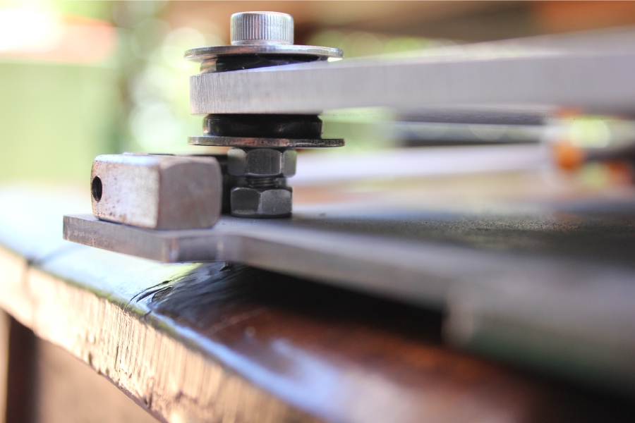
    Below you see the 4mm steel floor of the power supply with a 20mm gap to the 6mm aluminium platform.  The platform itself is isolated using a pair of sorbothane bushings which ensure that there is no easy path for vibration to take between the aluminium platform and anything else.  there is no direct physical contact between the 6mm bolt and the aluminium platform.

    Isolation Method.jpg
  6. The top plate through which the valves emerge is 8mm thick aluminium.  There are a couple of reasons for this, one of them is that it makes a particular aspect of construction a little easier than a thinner plate, but it also makes for a relatively rigid roof on the amplifier.  Immediately below this is a 4mm steel rafter onto which the valves are attached which also attaches to the 8mm aluminium top plate to form a CLD of its own, which should be reasonably effective at further dampening vibrations at the valve sockets.

So, if my plans work as well as I hope they do, the amplifier will be well isolated from structural vibrations originating in the horn stack or floor of the room.  The amplifier chassis itself is very high mass and high stiffness with lots of damping that is effective from about 100Hz up, with low coupling from the internal magnetics which in turn should be suitably isolated from the chassis by the sorbothane bushings.  

As far as I can see the only thing left to worry about is the effect of airborne vibrations directly to the valves from the sound of the speakers themselves.  After the chassis has been made as inert as possible in order to store as little energy as possible and release it later as vibration, which is has, then this essentially becomes a placement in the room issue.  There is nothing that anyone can do to eliminate airborne vibration from below about 100Hz...mass does not work and damping is relatively ineffective at these frequencies.  The best solution is to place the amplifers outside the room, which is not feasible here, and even then most of the sub 50Hz will just go straight through the walls with little attenuation and still cause the valves to vibrate.  The best I can hope for here is that I find a spot for the speakers in the room where the valves sit in some nice room nulls.

The horns are quite directional and frequencies above 200Hz or so will be quite attenuated behind the speakers themselves.  
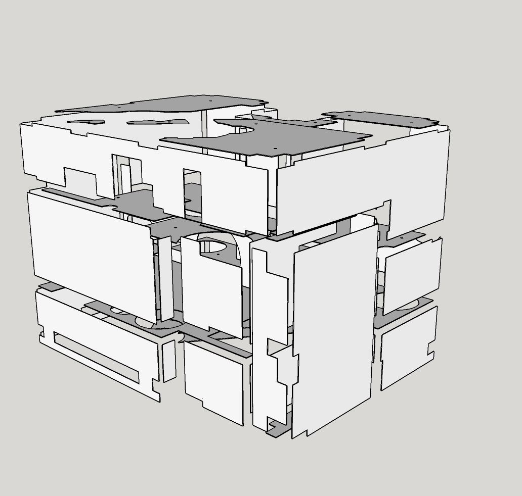
N-Set, I just use Google Sketch for my visualisations.  I work in AutoCAD for my work, but felt that I could do this home stuff on some free software so that I did not have to buy a subscription to the Autodesk 3D modelling software.
04-17-2017 Post does not mapped to Knowledge Tree
N-set
Gdansk, Poland
Posts 609
Joined on 01-07-2006

Post #: 112
Post ID: 23160
Reply to: 23159
Multiplying by zero
Anthony, irrespectively of all the extreme acrobatics you are doing with the inner damping and the structural isolation, sound wave hitting your tubes
can multiply all your work by zero. As simple as that. Big tubes = big inner structure structure = lots of possibilities to catch vibrations.
This can cause signal modulation and in extreme cases the microphone effect.
Can you somehow model the sound field at your desired amp location? Perhaps the tubes will happen to be in some shadow? 
It is your project, but if it was mine, I'd detach the amps from the horns, leaving some freedom with the amp positioning.
Or you can try making them detachable: You do what you planned and if the sound field is too strong, you detach the amps
and try to find them a more quiet location.

Which CAD software are you using? 

Cheers


Cheers,
Jarek
STACORE
04-17-2017 Post does not mapped to Knowledge Tree
Paul S
San Diego, California, USA
Posts 2,570
Joined on 10-12-2006

Post #: 113
Post ID: 23161
Reply to: 23159
Electro-Magnetic Fields
Anthony, it sounds like you have given a lot of thought to damping structural vibration.  I was referring to the electro-magnetic fields thrown by transformers, and - based on my view of your perspective drawings -  I was wondering if you had also taken steps to isolate tubes from this EMF?


Best regards,
Paul S
04-17-2017 Post does not mapped to Knowledge Tree
anthony
Posts 335
Joined on 08-18-2014

Post #: 114
Post ID: 23162
Reply to: 23160
Valve damping

I would contend that most of the microphonics and feedback in valves is usually caused by the resonances and vibrations of whatever they are plugged into.  Glass is very rigid which is only enforced by the shape into which it is molded.  Sure, sound pressure waves directly contacting the valve internals can cause the internal valve structure to resonate, I am not disputing this at all, but an amplifier chassis is generally less rigid than the valve, has a much larger surface area for pressure variations to induce vibration and is often a good mechanism by which energy can be stored for later release.  My "extreme acrobatics" have been aimed at producing as inert a chassis as I reasonably can so that the largest source of valve vibration feedback (in my opinion of course) is managed to some degree.

Then there is the feedback caused by direct sound onto the valve.  The quietest part of the entire room is probably immediately behind the horns.  After all, the horns manage their increased sensitivity by narrowing the dispersion of the driver and at all frequencies above the Schroeder Frequency for the given room behind the horn is significantly quieter than in front of the horn especially given the high mass of my horns and their reduced sound transmission through the horn walls.  Therefore, the only frequencies that I am worried about at this stage occur in the frequency range below the Schroeder Frequency where room pressure nodes occur, which is where the wavelength of sound is greater than a room dimension and pressure nodes and nulls will occur based on the characteristics of the room.  These frequencies are generally below about 200Hz and are nearly impossible to dampen wherever you place the valve in the room.  

So the big question becomes where the speakers will be situated within the room for best sound and does that correlate to a generally less or more low frequency pressure at the valves?  I have no way to tell, modelling will not work but empirical testing will give an indication (take SPL measurements at the amplifier).  Of course not all low frequencies have nodes and nulls at the same locations so the results will be 'average' based rather than for a specific best location for low SPL.  The amplifiers can be disassociated from the horn stack, that is not too difficult, but I really doubt that will be necessary and I really do not want to do it.  What might end up happening is I find the best positions in the room for the horn stacks and then see what happens when I integrate the bass arrays.  That is a bridge to cross at that particular time and if I have problems with the amps sitting in too many pressure nodes then I will have to reassess.  But I do not expect any issues from sound wrapping back from the horn stack, because apart from the lowest octave (100Hz - 200Hz) that will probably just not happen to any significant degree.
04-17-2017 Post does not mapped to Knowledge Tree
anthony
Posts 335
Joined on 08-18-2014

Post #: 115
Post ID: 23163
Reply to: 23161
EM radiation
 Paul S wrote:
Anthony, it sounds like you have given a lot of thought to damping structural vibration.  I was referring to the electro-magnetic fields thrown by transformers, and - based on my view of your perspective drawings -  I was wondering if you had also taken steps to isolate tubes from this EMF?


Best regards,
Paul S

Hi Paul,

Well, I feel that the largest step is getting the power supplies and chokes in a separate steel chassis away from the amplifier itself.  How far away depends on the length of the cables I construct.  When I discussed this with Lucas, the guy that wound nearly all my iron, he advised that there will be a significant EM field particularly in the power supply, but that it should mostly be taken care of by using a steel skinned chassis for both the power supply and amplifier and also by separation between the two boxes.

Inside the amplifier itself the only iron is in the filter chokes and output transformers.  The filter chokes are potted into heavy steel cases making them quite well shielded.  The filter for the Raal HF channel has two air caps and two shielded inductors inside a RFI screened box which sits again inside a steel sarcophagus just to be cautious...I remember reading about how much trouble unshielded filter chokes and air-caps gave Romy so I have been particularly pedantic in my situation.

The OPTs, as previously mentioned, have large physical separations from anything with which to magnetically couple.  The best that I could do regarding the RF and EM fields is physical separation.  I did design up a case that had each OPT sitting in its own steel box but in the end I was worried about heat and canned that thought and just went with a larger case and more physical separation.  Is it enough?  I think so and I hope so.  Lucas advised me to keep the Bass OPT at least 50mm from anything, so I have kept it 75mm from anything.

As for specifically shielding the tubes from internal EM radiation, I have taken no steps apart from separation.  Is there anything in particular that you think I should be looking at doing Paul?

Anthony
04-17-2017 Post does not mapped to Knowledge Tree
anthony
Posts 335
Joined on 08-18-2014

Post #: 116
Post ID: 23164
Reply to: 23160
It's free
 N-set wrote:


Which CAD software are you using? 


Google SketchUp.
04-18-2017 Post does not mapped to Knowledge Tree
Paul S
San Diego, California, USA
Posts 2,570
Joined on 10-12-2006

Post #: 117
Post ID: 23165
Reply to: 23163
Gauss
Anthony, I asked because I could not gauge distance from the tube pins to what I took to be large inductors shown straight underneath them.  Distance will do it, but I think the critical distance will vary, depending on the strength and "pattern" of the field thrown by the transformer(s) in question, and how inductive (or capacitive) the object one wishes to shield.  I have no experience with transformers straight below tube pins, but the sight of it raised my hackles.  In this case, it appears that air flow through the chassis depends on one level being open to the next, and the 6C33Cs need cooling, as well.  Of course you want a short run from the output tube to the OPT, but I wonder about straight underneath.  Maybe someone else has already tried this?

Best regards,
Paul S
04-18-2017 Post does not mapped to Knowledge Tree
anthony
Posts 335
Joined on 08-18-2014

Post #: 118
Post ID: 23166
Reply to: 23165
Mmmm...
...you've got me thinking about this now.  I'll talk to some people here and see what they think, but it should be easy enough to place a shield between the OPT's and the tube bases.

Thanks for bringing it up.  I am looking for other angles to view the design, and yourself and Jarek have been very helpful.
04-18-2017 Post does not mapped to Knowledge Tree
Paul S
San Diego, California, USA
Posts 2,570
Joined on 10-12-2006

Post #: 119
Post ID: 23167
Reply to: 23166
Without Looking Again
I don't remember exactly how yours were placed, but - while we're on the subject -  it is considered good practice to put the magnetic axes of proximate transformers at right angles to one another.  It's also good practice to attach dropping resistors, etc. directly to tube pin sockets, straight underneath them, which would effectively increase the depth of the tube below the deck.

Best regards,
Paul S
04-18-2017 Post does not mapped to Knowledge Tree
Romy the Cat


Boston, MA
Posts 10,049
Joined on 05-27-2004

Post #: 120
Post ID: 23168
Reply to: 23167
Something I observe…
There are 3 thing about which I would like to share my view 
 
1) Air vibrations transmitted to the amp. I do understand concerns about vibration transmitted over hard surfaces. The vibrations transmitted over the air? I do not think so. I personally do not buy it.  
 
2) The EM field. I think it is valid. The channels will have a lot of efficiency and at 110dB you need a juts a few mV to hear noise. In case of unpleasant loop is formed the voice coil at 110dB will act as a super sensitive antenna…  
 
3) Location of the last caps. This is VERY important. In the sketches at the last page Anthony show that the last electrolytic caps are located at PS side. This is not good. The last cap much be located as close as possible to the load as the cap is the path where AC will be shorted to ground. You do not want this path to ground to be over the long cable from amp to PS.


"I wish I could score everything for horns." - Richard Wagner. "Our writing equipment takes part in the forming of our thoughts." - Friedrich Nietzsche
Page 6 of 10 (187 items) Select Pages:  « First ... « 4 5 6 7 8 » ... Last »
Home Page  |  Last 24Hours  | Search  |  SiteMap  | Questions or Problems | Copyright Note
The content of all messages within the Forums Copyright © by authors of the posts