| Search | Login/Register
   Home » Melquiades Amplifier » Single-stage Melquiades vs. DHT amps (398 posts, 19 pages)
  Print Thread | 1st Post |  
Page 12 of 20 (398 items) Select Pages:  « First ... « 10 11 12 13 14 » ... Last »
   Target    Threads for related reading   Most recent post in related threads   Forum  Replies   Views   Started 
  »  New  DHT driver & input..  Effects of radiation...  Melquiades Amplifier  Forum     25  238955  02-01-2007
  »  New  The one-stage Melquiades...  It's time, what amorphous opt...  Melquiades Amplifier  Forum     74  658219  04-21-2007
  »  New  The single-stage Milq and power Supplies...  Just the tank...  Melquiades Amplifier  Forum     10  96194  05-03-2007
  »  New  The 6E5P tube data...  Bartola Valves: 6e5p beam tetrode SPICE model...  Melquiades Amplifier  Forum     44  465964  07-23-2007
  »  New  6 Channel Version of Super Melquiades..  The first Milq screw up....  Melquiades Amplifier  Forum     131  1208326  08-08-2007
  »  New  My (Amplification + Acoustic System): what is next?..  Macondo and Melquiades in the NEW room....  Audio Discussions  Forum     41  302720  01-10-2008
  »  New  Incorporating active crossovers into DSET..  Thanks...  Melquiades Amplifier  Forum     2  44202  07-22-2008
  »  New  About the life-expectancy of the new production tubes...  Stressing the damn contemporary tubes....  Audio Discussions  Forum     9  90060  12-29-2008
  »  New  Small SET’s bass, besides everything- is it about power..  Importance of OPT and type of tube for SET amp bass per...  Audio Discussions  Forum     4  83074  01-12-2009
  »  New  Macondo: new horizons. A few thoughts in context Zander..  What does make a playback to stop?...  Playback Listening  Forum     9  72642  02-02-2009
  »  New  The period DHT tubes and Swastika..  Maybe there is another solution...  Melquiades Amplifier  Forum     1  27432  04-30-2009
  »  New  Some thoughts about Milq’s MF filter..  High-Pass RL Filter calculator....  Melquiades Amplifier  Forum     2  33556  05-02-2009
  »  New  The DHOFT topology? Do not try it home...  A medley of slow-cooked triodes....  Melquiades Amplifier  Forum     3  46881  05-04-2009
  »  New  Why the tubes shall be the same?..  Not optional anymore?...  Melquiades Amplifier  Forum     7  62284  05-11-2009
  »  New  Valve Technology Timeline..  A good video about tubes making....  Audio Discussions  Forum     5  95558  06-18-2006
  »  New  The DSET perspective examines the Herb Reichert article..  Are you still in Reutlingen, Germany?...  Melquiades Amplifier  Forum     5  94280  07-01-2009
  »  New  About the Critical Audio Tune ™..  “Critical Audio Tune” bay-leave in the soup......  Playback Listening  Forum     5  50907  08-29-2009
  »  New  A full-range quality-triode? Does Size mater?..  A full-range quality-triode? Does Size mater?...  Melquiades Amplifier  Forum     0  17026  12-02-2009
  »  New  About Stupid Dynamic..  Misplaced dynamics....  Playback Listening  Forum     1  21078  08-21-2011
04-14-2009 Post does not mapped to Knowledge Tree
floobydust


currently roaming the US
Posts 62
Joined on 01-19-2009

Post #: 221
Post ID: 10228
Reply to: 10227
Simple is good
fiogf49gjkf0d
 From my view, I would add a dedicated filament transformer for the DHT. It's clean, simple and a known performer. I'd also be inclined to drop the support of a 6A and stick to a 2A3 only. Alternately, if you have no need for a center-tap on the DHT filament transformer, than you could use a pair of dropping resistors for the 2A3 and only add one transformer (4VAC).

 Regards, KM


... just because you're paranoid, it doesn't mean they're not after you ...
04-14-2009 Post does not mapped to Knowledge Tree
Romy the Cat


Boston, MA
Posts 10,052
Joined on 05-27-2004

Post #: 222
Post ID: 10230
Reply to: 10228
Ok, I am moving forward.
fiogf49gjkf0d

Well, I do not know what DHT filament scenario I will choose. I consulted with different sources

http://www.intactaudio.com/forum/viewtopic.php?t=823

…but I still have no definitive opinion. There are few logical cons and pros for different implementation scenario and although I do have a bias to go for a dedicated DHT filament transformer but no one talks about the results in term of sound. So, I decide to try BOTH dedicated and decoupling transformers. Both of them have ordered, will see where it will lend me…

Meanwhile I took a temporary dedicated 6.3V 25A transformer that was laying around and put the DHT Milq together. It worked very fine. I did not listen the amp yet but rather just was observing how both 2A3 and YO186 work together in the SAME operation point.  They do OK, here are the numbers:

The 2A3, the Sovtech one for now: 315V on anode, 51.5V dropped on cathode resistor, which lives for the tube 263V.5. The plate current 43mA with anode dissipation 11.3W

The YO186: 317V on anode, 49.9V dropped on cathode resistor, which lives for the tube 267V.5. The plate current 49.9mA with anode dissipation 13.3W

It looks OK, but I probably will drive YO186 a bit softer, let say at 11W.  I can wait to start listen this thing…

The Cat


"I wish I could score everything for horns." - Richard Wagner. "Our writing equipment takes part in the forming of our thoughts." - Friedrich Nietzsche
04-15-2009 Post does not mapped to Knowledge Tree
Romy the Cat


Boston, MA
Posts 10,052
Joined on 05-27-2004

Post #: 223
Post ID: 10238
Reply to: 10230
The Milq DSET is up.
fiogf49gjkf0d
Ok, I connected the DH DSET channel into the main Melquiades amp driving the DHT from a separate transformer. Until the final transformers arrive I will be able to test and to measure DH circuit, perhaps finding better operation. I connected to the DHT my favorite test speakers. You can see it on the picture – it is my absolutely the most beloved MF test driver – I would LOVE to find the second one but I do not know where. The 2A3 sounds fine, the YO186 might be just swapped in the same operation condition and it sound fine as well. Even with my test driver it is already well auditable that YO186 is VERY differently sounding tube.

I faced only one problem about which I did not think. The top lead on which I hosted everything must not host the transformers as my transformers are referenced to cathode ground not to the chassis ground. So, I need to found a way to mount all transformers but to isolate them from chassis (so far I isolated it by t-short). I think I need to hunt some nylon bolts… Oh well

MilqDSET_FirstBlood.JPG

The Cat


"I wish I could score everything for horns." - Richard Wagner. "Our writing equipment takes part in the forming of our thoughts." - Friedrich Nietzsche
04-17-2009 Post does not mapped to Knowledge Tree
Romy the Cat


Boston, MA
Posts 10,052
Joined on 05-27-2004

Post #: 224
Post ID: 10245
Reply to: 10238
My DH DSET – 2 days later.
fiogf49gjkf0d

I made experiments running HF filaments from dedicated Hammond 6.3V transformer vs. lifting ground on my 6.3V IDH filaments. I did not listen Sound but rather measure the noise – the result was identical. In the best cases I was able to get 0.63mV at output – way bayonet of what I need to worry even with 109dB sensitivity. In practical term I prefer the lifting ground on my large 6.3V IDH filaments secondary. What I drive my HT filaments from a separate desiccated transformer then I need to be very accurate with grounds as I have 1.2K resistor between amps ground and the HD filaments. Any problem as the cathode of DH tube accept ground potential and plate current of the tube run away to 100s mA. I have a couple of accidents like this running accidently the Sovtech 2A3 at 100s mA. The good part that the large 20W 1.8K PS resistor act as a fuse … unsoldering itself from the circuit. To my surprised the immune to sound Sovtech 2A3 is still operation after of few stresses like that.

With the floating the secondary of my 6.3V IDH filaments I can do whatever I want and there is no damage to DH bias, or a need to isolate anything. Thinking further I realized that if I use a dedicated DH transformer of floating the secondary of my IDHT then in both cases I use my cathode resistor on DHT as biasing resistor for my heaters. It might not sound kosher but it is what it is in all cases. I have a dedicated better made filament transformer (bile like audio transformer) coming next week as well as filaments isolated (6.3V to 4V) transformer coming. I will see what they do in terms of Sound but I think I do not have a fear anymore to use my cathode resistor as bias for IDHT filaments.

There are however more complication then that. I made some fine adjustments in values and now I have both tubes 2A3 and YO186 runs 41mA . Here is the new draft of the circuit:

Melquiades_YO-186_Draft3.jpg

The operation is very stable and there is no noise. The amp produce OK sound (to my little control monitor, not to my main playback) and I have to tell you that the idea to have an amp with both tube sockets was brilliant idea. It is so cool that I might just name it and I have no idea why others do not do it.  The plate impedances of those tubes are very close and the amp might have as well the sockets for 300B/45 or AD1. Just shut down the amp, plug a new tube, adjust lowest amount of AC mV on the OPT secondary via the filaments attenuator and here we go…

Now is the problem. My DH DSET measures like crap. I did not go deep into it yet, will do obviously. I was running the sine wave trying to determine the LF cut off and making sure that the amp’s filter kicks in before both of transformers clipping will come to the picture. It was fine. I am running the Innerstage transformer for now as 2:1 and I was measuring with my scope with AC voltage that driver stage delegate to DHT’s grid. It was fine as well – it sits deep in A1. Something made me then to switch the generator into square wave and to see what amp outputs. Holy cow it is something absolutely not identifiable – at all frequencies with all amplitude. At 10K the amp shell do very good square wave but in my case it was a nightmare.  I do not know at this point what is ringing in there: the input filter (highly unlikely), the Innerstage transformer, the output transformer, the secondary of the Innerstage need additional damping, or something else. I know that until I have the acceptable square wave from my DSET then I would not even make any attempt to listen the thing. This is over 3.2kHz DSET it shell be handling square wave very fine throughout it’s whole range.  I need to blow each stage and each transformer with squares individually to find out what is the problem with this amp so far…

Well, I hoped that to make this Milq HD DSET will be a walk in a park, a plug and play ceremony - it does not looks like that so far.
The Cat


"I wish I could score everything for horns." - Richard Wagner. "Our writing equipment takes part in the forming of our thoughts." - Friedrich Nietzsche
04-17-2009 Post does not mapped to Knowledge Tree
Romy the Cat


Boston, MA
Posts 10,052
Joined on 05-27-2004

Post #: 225
Post ID: 10250
Reply to: 10245
Here is more data to reconcile.
fiogf49gjkf0d

The voltages on the schematics are the actual live voltages driving a full power 5000kHz. The next 10mV at input clip the amp. I do not know yet what clip first’ driver stage, output stage of any of transformers. Anyhow, the full power set as a full 10 squares on the scope

Melquiades_YO-186_Draft4.jpg

Here I drive the same voltage all the way up until it hit -3dB. It is 23kHz. 

Melquiades_YO-186_Draft4_23k.jpg

Then I drive the same voltage all the way down. The -3dB is at 2.4K

Melquiades_YO-186_Draft4_2.4k.jpg

What is interesting is to drive the channel with something where transformers have no inductance. I took 500Hz. It is many dBs down and I added a lot of v/div. Still if spread it over the full screen then the distortions are visible but the tops are not clips – that is indication that the filter roles fast then minimum inductance – a good sign

Melquiades_YO-186_Draft4_.5k.jpg

What I do not like is below. This is a square wave into 5K that is perfectly in band-path. I did measured the same after the driver stage and blocking cap with 15K resistor on plate driven from 400V and the squares were MUCH better. So, it is not the filter and not driver state.

Melquiades_YO-186_Draft4_Square.jpg

I was loading the inner stage secondary and it has no impact…

The Cat


"I wish I could score everything for horns." - Richard Wagner. "Our writing equipment takes part in the forming of our thoughts." - Friedrich Nietzsche
04-18-2009 Post does not mapped to Knowledge Tree
Romy the Cat


Boston, MA
Posts 10,052
Joined on 05-27-2004

Post #: 226
Post ID: 10252
Reply to: 10250
Hm, that is interesting and unpleasant so far.
fiogf49gjkf0d

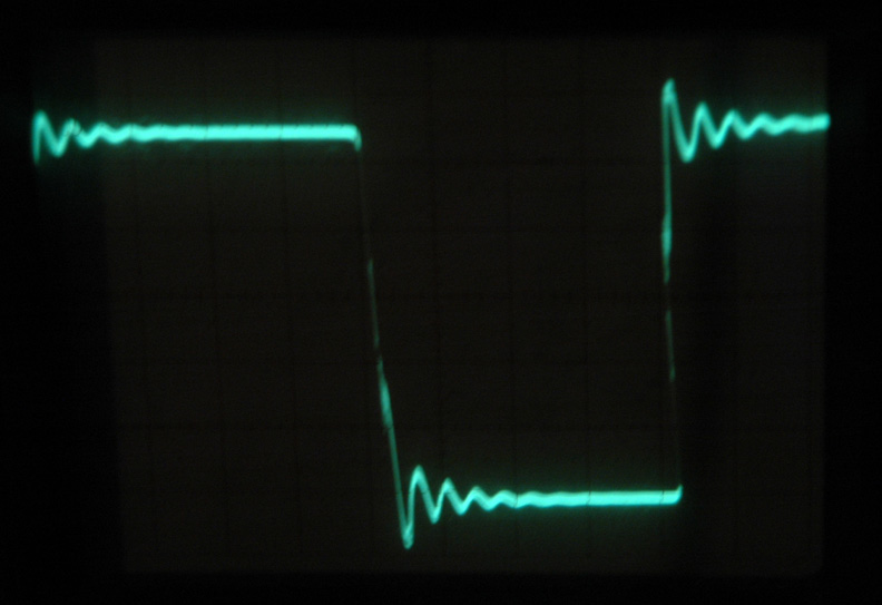
I was searching for an answer why squire wave is so screwed and I was advised by the site’s visitors that it is due to HF restriction of my channel. My HF response does look too low to me – the 23kHz; with all my ultra low capacitance magnetic I was expected way higher.

Something is not right. So, I decided to look at the stages independently.

First I looked at the output stage. I shunted the grid of 2A3 with 250K to ground and put 2uF cap between grid and generator.  Unfortunately my generator can’t swing more than 10V and I was not able to drive the tube into full power. With 10V on grid the 2A3 just started to roll off at 275kHz, but picked a lot of distortions. The clean and not distorted sine wave I got somewhere up to 140kHz, that is meaningless as it was not at full power. So, I drove squire wave there the thing at 10kHz. This time it was tutorial different picture. Obviously the output stage was fast enough and was not the problem of my initial squire wave.

Melquiades_YO-186_Draft4_Output.jpg

Then it might be the transformer. I still do not know why that transformer in 2:1 configuration gives 30% of voltage lost. Who know, might be something else wring with it? I got rid the grid resistor and coupling cap and put the coupling transformer in, driving transformer’s primary from generator

Melquiades_YO-186_Draft4_Transformer+Output.jpg

It looks like the transformer did restrict HF up to the point as I had in the post above. So, the driver stage was one that left. I put 15K anode resistor on the driver stage, drove it from 400V and took output via a coupling cap. Here I had my 23K restriction and screwed squire wave. Hm, it looks like my line-level filter plays a bad game with me introducing too high impedance on the driver’s grid that along with tube miller capacitance of the driver tube shape low-path filter. The original Milq bias had 8.2K grid resistor, now the idea evolved to 32.1K for HF channels.

http://www.goodsoundclub.com/PDF/6-Chennal_Melquiades_DSET_Amplifier.pdf

Well, I need to think about it.  For MF I need the 20K resistor to write the high-pass filter. I can get rid the input filter all together, keeping just 10K-12K impedance on grid (that would give me around 50kHz response) and then I can make the same high-pass filter with coupling cap.  I am a bit afraid this solution as I had problem with sound in this configuration before, when the inner-stage caps acting as filter did not sound right for HF

http://www.goodsoundclub.com/GetPost.aspx?PostID=1234

also, I do not like the idea of coupling cap as with my 33 time gain in driver stage it will deliver too high voltage to the 2A3 grid and I would not wont to be involved into the coupling cap recharging and A2 operations. I might drop voltage on the driver’s grid that will again introduce too high impedance on the grid…

Frankly here is where the 6E5P gain works against me. To use the high gain, current capable driver did make sense for two-stages around 6C33C that has 60-80V on grid but with those flimsy DHT with 40V on grid I would prefer to have 15-20 time gain in driver, something like a half of 6SN7 or alike.

I kind of do not know where to go from here and I did not even start to listen the thing. I am trying to interpret the result I was getting up to now. The original Melquiades idea was perfect but then the value of the grid resistor begins to grow to 10K and then 12.1K and then to 30K that included the high-pass filter. Unknowledgeably to me the HF response of the channel was lowering from above half- hundred KHz to 23Khz. Parallel to it I was loading the MF stage harder and harder from 1.2K on 6C33C (that is VERY idea for that tube) to something that is equivalent  to 450R – a very heavy load.

I might understand why I went this way – I use Vitavox S2 drive that is very fast, very contrasty and that might go into some harshness if it not handled properly. Everyone who use S2 have problem with it but I do not. My S2 is very smooth and superbly eloquent. I was under presumption that I accomplished it by loading the stage that drive S2 but now it look like I also used less fast amp to drive the S2. It might be even beneficial but I am a bit distracted by the fact that when I switched my Sun Audio 2A3 prototype amp from cathode-biased 6SN7 to grid-biased 6E5P I did observed some transformation in transients reproduction. The cathode-biased 6SN7 has no HF limit but the grid-biased 6E5P with 12.1K resistor is effectively a low-pass filter at ~35K. Add to it the roll off of the transformer and we have second order low-pass. Well, I need to reconcile all of it and figure out how much HF I would need in MF channel.  The whole objective of the experiment of conversion the Milq to DHT MF was to inject live more into MF. My presumption was that my single stage tube has no power and no gain to be loaded idle-enough to have good transients. However, it might be ALSO the problem is not with the single stage itself but with the fact the MY CURRENT IMPLEMENTATION of single stage has too aggressive low-pass making the amp not able to throw good transient characteristic.

Hm, this opens a wide thinking about the other opportunities…

Unquestionably in the original Milq the cathode-bias or fix bias did not sound even close to grid-bias. In context of full range the grid-bias literally destroyed all other options… with THIS tube. Would it be because my driver tube itself is very fast (275MHz) and my grid-bias calmed the tube down a bit?

Well, there are many thoughts in my head at this point and I need to think what to do with my MF channel next. I even thought to DC coupe the driver and DHT, why not? I have 400V supple to drive the DHT. If I burn the 150V on DHT cathode and drive the driver at 200V on plate then I can direct-couple them. It will be no drift for PS as my whole amps is driven from AC-stabilized regenerator (good for PP2000). All DC instability might be handles and I never seen my 6E5P to die catastrophically, so nothing will burn out the output stage. It will not however address the problem with the driver stage’s low-pass… To use slower tube with less gain? To go cathode bias on 6E5P but then I need to target impedance to write my line level filter? To go with a cap filtration instead of RL filtration? To go full-range super fast amp and use speaker level filter? I do not like any of the options so far.

That all is very interesting and unpleasant so far. I did not think that the DHT projects would open so many skeletons in the Melquiades closet.

The Cat


"I wish I could score everything for horns." - Richard Wagner. "Our writing equipment takes part in the forming of our thoughts." - Friedrich Nietzsche
04-18-2009 Post does not mapped to Knowledge Tree
Romy the Cat


Boston, MA
Posts 10,052
Joined on 05-27-2004

Post #: 227
Post ID: 10253
Reply to: 10252
Ok, what do I want?
fiogf49gjkf0d

Well, I kind of understand that my objectives for my “perfect” MF channel I have some irreconcilable differences.  Let see:

1)      No capacitors in signal path

2)      Bandwidth restriction, allowing employ DSET type output transformer with minimal inductance.

Sounds simple but it implies use of front filter that automatically implies impedance.  Is it possible to write a filter with of cathode or anode voltage? How about use of substation filter at line-level? The most important - do benefits that I get from use the DSET type output transformer over-weight the problem I get using the line-level filtration? The speaker-level 3uF filter on Vitavox driver works under high current and had less damns to any cap at line level of between stages. That however convert the amp into a full range – not the direction I would like to go.

Options, options, options… I still have no topology that would grab me conceptually and… I am not convinced that my current configuration is something that would have subjective sonic problems on MF.

The Cat


"I wish I could score everything for horns." - Richard Wagner. "Our writing equipment takes part in the forming of our thoughts." - Friedrich Nietzsche
04-18-2009 Post does not mapped to Knowledge Tree
Paul S
San Diego, California, USA
Posts 2,577
Joined on 10-12-2006

Post #: 228
Post ID: 10254
Reply to: 10253
Let Go of Some Conceptual "Restrictions"?
fiogf49gjkf0d

Still using 6E6P for driver?  Can you just scrub some gain with lower plate values without making such a steep signal path filter?  You'll still be forced to tailor your bandwidth, of course.

Would it help to split the roll-off curve between the stages, maybe step down?

FWIW, I'll bet most of us wind up living with a +/- traditional RC coupler, with a cap in the signal path.

And maybe, given this particular situation, a speaker-level cap and "FR" output to drive it is not really such a problem (except if you need to order another tranny...), since you hardly have to worry about FR, after all, if the cut-off slope is gradual enough.

According to Ohm's Law, that "lost" voltage is going somewhere...

Best regards,
Paul S

04-18-2009 Post does not mapped to Knowledge Tree
Romy the Cat


Boston, MA
Posts 10,052
Joined on 05-27-2004

Post #: 229
Post ID: 10256
Reply to: 10253
The Milq DH DSET, the further thoughts in progress.
fiogf49gjkf0d

Ok, I made some further experiments driving this time my S2 driver from Milq DH DSET. The hell of the sensitively - it was too much.  So, I went for 4:1 inner-stage ratio. The result was very successful and the amp looks like was able to get more voltage in. Now it clips at higher power at bottom half (I do not remember it is voltage or current and I did not get yet which stage or what transformer clips first it will be fun to learn in future).  Take a look what I have now:

Melquiades_YO-186_Draft5.jpg

The good part is that 4.3V at input is it how much my DAC outputs at -2dB digital. With this volume window of my room will fly away along with frames – I never play that loud. Even at this level I have a driver and the power stage run at half of the grid bias- very good.  The bad part is that I pump a hell of a lot gain in the driver stage and then burn it in innerstage transformers. Well, it is not just do not make sense but it also have relation to my other thoughts…

My other thoughts were that I was listening today my MF channel driver from Milq DH DSET. I actually was listing the Sound.

Melquiades_YO-186_Draft5_MET.jpg

I like Sound more then I had it with a single stage but it is also not the sound that I would like to have. I have a LOT of to say about the sound of Milq DH DSET with 2A3 and YO186 and about the DH specific but I will do it later what I will be taking about Sound.  So far I am not in Sound mode but I rather looking for first an intellectual stimulating solution of my topological problem.

The subjective initial assessment of sound suggests that although the sound with DH is better but it still the same type of sound – it is gracious, polite and fabulously smooth. With the DH it has some interesting texture and other thing that I will comment about later but it is still a bit on “save side”.

As you might read in my post above I discovered recently that my elaborate Milq-biasing, and filtering crate too much impedance on the grid and consequentially too closer low-pass filer. The ugly square wave response of the driver stage proves it.  So, that all make me to wonder….

Let see, the high impedance on the grid create the filer as it work with Miller capacitance. The Miller capacitance is the plate-to-grid capacitance multiplied by gain plus one.  The 6E6P has 15pf and 33 times gain makes is near 500pF. The 500pF in tube and 32.1K in grid is what I have my 23kHz response and the ugly square wave. Now, I DO NOT claim that the making my MF amp faster in trims of upper frequency response is something that I need and is something that would me to feel better about sound. But it might be the case as the better square usually relates to better transients.

OK, too high capacitance too high impedance and too much gain… the answer is self-evident – I might to look for another driver stage.  The 6E5P/6E6P is voltage tube but I do not need a lot of voltage to drive my DHT. If I look for a new driver then here are some requirements:

1)      Good sound – it shell not be explained further.

2)      Bias or 2-3V that will be left from 4-5V input voltage left after filter.

3)      ability to work with fixed bias

4)      200V on plate

5)      Low Miller capacitance as it still use the filter and prefabs the Milq bias

So, I was looking around and thinking about the the Russian 6N6P. The 6N6P is Russian version of 5687. Bothe tubes  are wonderful sounding but the 6N6P reportedly (not my report) is better as it has more parallel plated vs. the 5687 that has it curved. The 6N6P has 2V bias that would make Milq’s grid bias to be twice lower. I would like to have it 3V to have some spare voltage but you will never know how much it will be unless you try. The 6N6P is double triode and each half has 4.4pF of input capacitance. That is very great as it 3 times lover then my current 6E6P. The 6N6P has gain of 20 that would make the total Miller capacitance of 88pF. The 88pF vs. 500pF – only that will give me way more extend response. Oh, did I tell you that I have around 50 6E6P in my storage?

http://www.goodsoundclub.com/PDF/6N6P.pdf

I do not have a decision yet. I might convert one channel of my Sun Audio prototype amp. But at this point I am opone for options…

The Cat


"I wish I could score everything for horns." - Richard Wagner. "Our writing equipment takes part in the forming of our thoughts." - Friedrich Nietzsche
04-18-2009 Post does not mapped to Knowledge Tree
Paul S
San Diego, California, USA
Posts 2,577
Joined on 10-12-2006

Post #: 230
Post ID: 10257
Reply to: 10256
Crunching Numbers; Shaping Sound
fiogf49gjkf0d
I'm way too lazy to double check the math, but it looks on the face of it like the 6N6P is one answer to the numerical problems you've posed so far.

As for sound, I would prefer the best 6SN7s.  But who can find them and who can afford them, once they're found?

Also, to be fair, I have never played with 6N6P operating points.  It may well be that it can be tweaked and optimized in a given circuit, just like the tubes I have played with in order to get the most out of them.  The 6DJ8 is an example of a "lowly" tube that changes sound character dramatically according not only to operating points but it also gets down to the particular resistors used to load it.  Maybe the 6N6P is similar?

Another feature is that you can strap the plates or run parallel, for more gain or still lower impedance.

Best regards,
Paul S
04-19-2009 Post does not mapped to Knowledge Tree
Romy the Cat


Boston, MA
Posts 10,052
Joined on 05-27-2004

Post #: 231
Post ID: 10258
Reply to: 10256
How about the tweeter?
fiogf49gjkf0d

I have to admit that although the Macondo “Water Drop Tweeter” sounds very good but I do not have that “shocking sound” that I got from the “Water Drop” during my initial introduction to it. I kind of always felt it and I thought that I get use to it but now I think differently. What is the problem is that in my current version of Milq my HF channel suffers from the same problem of low-passing die to the high grid impedance as I described above.

After all, the grid has the same 500pF of the 6E5P and 32.1K impedance… I can not test the “Water Drop” with other channel as it is direct to plate bound and I was thinking about the two stages and inner stage filtration. I hate to lose the super cleanness of a single stage for HF… and then it came to me: the 6E5P is a TETRODE. The Weekeipida says:

“The second grid, called "screen grid" or sometimes "shield grid", provides a screening effect, isolating the control grid from the anode. This helps to suppress unwanted oscillation, and to reduce an undesirable effect in triodes called the "Miller effect", where the gain of the tube causes a feedback effect which increases the apparent capacitance of the tube's grid, limiting the tube's high-frequency gain. In normal operation the screen grid is connected to a positive voltage, and bypassed to the cathode with a capacitor. This shields the grid from the anode, reducing Miller capacitance between those two electrodes to a very low level and improving the tube's gain at high frequencies. When the tetrode was introduced, a typical triode had a input capacitance of about 5 pF, but the screen grid reduced this capacitance to about 0.01 pF.”

Well, why do not flip my single 6E5P into tetrode?   The datasheet on 6E5P said that in tetrode mode it has 0.006pF. The gain will be higher. Let say 200, so it will be still under the whopping 1pF that will give me response over 100kHz. To do so I need juts to flip one wire on my 6E5P and to listen the result. If it works then it will be so elegant solution for tweeter!!!

The Cat

PS: BTW, can I ground the second screen of my TETRODE through an addition cap? The series caps theoretically lover summing capacitance, so my external cap might lower my Miller capacitance?


"I wish I could score everything for horns." - Richard Wagner. "Our writing equipment takes part in the forming of our thoughts." - Friedrich Nietzsche
04-19-2009 Post does not mapped to Knowledge Tree
Paul S
San Diego, California, USA
Posts 2,577
Joined on 10-12-2006

Post #: 232
Post ID: 10259
Reply to: 10258
Tweeter Efficiency?
fiogf49gjkf0d

Why not try it?  It "should" work to extend response, if nothing else.  Just use the least in the way of caps you can get by with, to avoid "breathing".  And it's not like you need the gain, if, as I recall, that tweeter is a 109 dB target.

Of course, there is the coil(s), as well, to factor in, since the load is direct...

Best regards,
Paul S

04-19-2009 Post does not mapped to Knowledge Tree
Paul S
San Diego, California, USA
Posts 2,577
Joined on 10-12-2006

Post #: 233
Post ID: 10260
Reply to: 10256
Safe and Sound
fiogf49gjkf0d

Probably not the best place to post this, but in response to the related observation in the referenced post:

How can we impliment the PS that seems always willing to blow itself up in service of the Music, if called upon to do so?

Perhaps when the raw power source is itself made to be uniformly acceptable, it is time to streamline equipment PS to the least that is functionally necessary, so it forms less of a "buffer" to the primal source?  Of course, this still presumes proper isolation, to avoid wholesale signal/PS interaction.

The only basis I have for this notion is that it seems like the better stuff resists the effects of bad electricity, the less "raw" potential it seems to have in terms of Sound character when electricity is good.

Paul S

04-19-2009 Post does not mapped to Knowledge Tree
Romy the Cat


Boston, MA
Posts 10,052
Joined on 05-27-2004

Post #: 234
Post ID: 10261
Reply to: 10258
More mystery with tweeter but still on the subject.
fiogf49gjkf0d
 Romy the Cat wrote:
I have to admit that although the Macondo “Water Drop Tweeter” sounds very good but I do not have that “shocking sound” that I got from the “Water Drop” during my initial introduction to it. I kind of always felt it and I thought that I get use to it but now I think differently. What is the problem is that in my current version of Milq my HF channel suffers from the same problem of low-passing die to the high grid impedance as I described above.
I swept my current tweeter configuration with generator and scope. It has second order filter came to play at 12KHz and has cursing 0dB at approximately 19KHz at full power (4V in input). The very same cursing 0dB got all the way up as I raised frequency, we stopped at 73KHz. So, despite it has the same as MF 32K on grid and the same driver but it has not low pass apparently. How that might happen. Furthermore, despite the HF has no limit but the square wave, although it is better but still has not “perfect” shape and in way reminds the squares of the MF channel above.

The Cat


"I wish I could score everything for horns." - Richard Wagner. "Our writing equipment takes part in the forming of our thoughts." - Friedrich Nietzsche
04-19-2009 Post does not mapped to Knowledge Tree
Romy the Cat


Boston, MA
Posts 10,052
Joined on 05-27-2004

Post #: 235
Post ID: 10262
Reply to: 10261
Some clarifications.
fiogf49gjkf0d
Ok, I have figured out why I have so extended bandwidth over 73kHz for my tweeter. I forgot that when I measured it I had the LPAD wide opened and in this configuration the parallel resistor is 20K and series is shorted. So, in that case I had just one 12K bias resistor against the grid and the full HF bandwidth of the original not restricted Milq. That explains the mystery part and my concerns with HF.

Now is the explanation of the idiocy part. I consulted with a friend of mine and dumped to him my dilemma with limited up to 23KHz bandwidth of MF and the ugly square wave. He listed me carefully and then asked: “So, what is the problem?”

According to him the HF limitation of my MF is perfectly reasonable and the square wave is very much what shall be expected. He explained that order to write the correct square wave via an amp the amp shell have at least 10 times extra bandwidth. If I have 5kHz square and try to do it with 20kHz bandwidth and at full amp neat clipping power then he would not expect anything different then what I got. I do not completely agree with him but his explanation certainly removed me from an alarmist position that something is wrong with my MF channel.

The greatest result after his explanation was that I might not blame the topology and HF restriction in the some minor subjective dissatisfaction from the Sound I am getting listing my new DH MF channel. It is not that I have dissatisfaction but I would like to have more “brisk”. Well, it suddenly come to me: perhaps I need to stop to make my assessment listening FM?  Anyhow, here what I think. I need to finish the amp with not temporarily hook up wire, not the temporarily prototype grounds and not to connecting the amp with 25” Radio Shake-bought interconnects and speaker cables. I mean I need to finish the DH channel as is with the same precision and accuracy as my single-stage MF channel is made on another amp and then to compare the results. If after then I’ll feel that I might stress my S2 driver more then I would go do for 25:1 coil for my output transformer. According to my measurements with 20:1 output transformer I need 3,5:1 innerstage transformer. If I go 25:1 or even insulting 30:1 then I will still have spare ration in my innerstage to release.

The Cat


"I wish I could score everything for horns." - Richard Wagner. "Our writing equipment takes part in the forming of our thoughts." - Friedrich Nietzsche
04-19-2009 Post does not mapped to Knowledge Tree
Romy the Cat


Boston, MA
Posts 10,052
Joined on 05-27-2004

Post #: 236
Post ID: 10264
Reply to: 10262
How about that?!!!
fiogf49gjkf0d
Suddenly a strike of geniuses hit me and I found a way to extend the bandwidth of Milq MF channel up to the standard for DSET extended level. I do not know if I need it and if I have any subjective benefits but I found that the solution is very elegant.  Take a look: this will remove all extra impedance from the driver’s grid.

Melquiades_YO-186_Draft6.jpg

The only question is if the change of current from tube to tube will lead to change inductance of primary. If yes then it leads to minute shift of crossover point and will time misalign my MF driver.  If no then I will have the Milq’s MF channel to have 50KHz -70KHz upper knee and softer decay at the bottom slope.


"I wish I could score everything for horns." - Richard Wagner. "Our writing equipment takes part in the forming of our thoughts." - Friedrich Nietzsche
04-21-2009 Post does not mapped to Knowledge Tree
Romy the Cat


Boston, MA
Posts 10,052
Joined on 05-27-2004

Post #: 237
Post ID: 10284
Reply to: 10264
Further considerations: DC-coupling.
fiogf49gjkf0d
I need to tell you that I did not finalize mu Milq DH DSET up to the point where I would listen it. Perhaps I am wrong but the amp even in the last version has some lack of agreeability. It is good on paper, it might even sound right when it will be finish but it does not feel as it might be the last solution for my MF. You see a right solution in my view address not one problem but a multitude of the different problems and I do not have that intellectual bliss for my current design.

Last night I was advised by willing to be anonymous collaborator a solution that would drop my grid impedance on driver tune and at the same time lover my grid AC voltage. That solution (if it sounds right) opens a Pandora Box for completely new way of thinking as it will eliminate my drive tube to force the power tube into class A2. If so, then why don’t I direct couple sages? The DC-coupled stage will be in fact the same one-stage DSET with input filter. This idea is very much on the working now. I do not particularly case about the full-range DC-coupled SETs. What whatever reasons among whatever DC-coupled I heard I always was bothered that harmonics ether of MF or in Bass were wrong. The amps were able to superb MF but with vacuum-like harmonics – very unpleasant. The bass of those amps is always too fast and too inhumane. Listening those amps I feel like am in anechoic chamber and people do a physiological experiment on me. However, my MF is not a full range amp but a DSET that case above 3200Hz. I might go away with it very nicely…

So, if it work I might preserve the super cleanness of my single stage and pick some alleged benefits of DHT… Let see what new days will bring  up….

The Cat


"I wish I could score everything for horns." - Richard Wagner. "Our writing equipment takes part in the forming of our thoughts." - Friedrich Nietzsche
04-21-2009 Post does not mapped to Knowledge Tree
Paul S
San Diego, California, USA
Posts 2,577
Joined on 10-12-2006

Post #: 238
Post ID: 10285
Reply to: 10284
Head Room
fiogf49gjkf0d
But who says an A2-capable amp should actually be driven into A2 in use?  I thought you planned to operate the amp well within its limits, to get the DHT benefits without subjecting the amp to the sorts of stress that always spoils these little things?

I don't know how clean your 1-stage amp is in use, or what it gives you for tone, but the gold standard for me has been an un-stressed 45 X 6SN7; clarity and tone, too (but very limited power, obviously).  I like the 2A3, too, but I only wound up with it to get more power, because the 45 was simply not practical FR (and neither was the 2A3, for that matter).  But then, I was not driving 109 dB speakers (and, like you say, you're not using it FR).

I forget, so please remind me again of the actual net sonic benefits from DC coupling a DHT/SET amp.  And does that ask anything different from your PS?

What did splitting the curve between the tubes, etc., wind up doing wrong?

Do you just hate the RC follower?

Best regards,
Paul S
04-22-2009 Post does not mapped to Knowledge Tree
Romy the Cat


Boston, MA
Posts 10,052
Joined on 05-27-2004

Post #: 239
Post ID: 10288
Reply to: 10285
To kill the mandatory 13dB
fiogf49gjkf0d
 Paul S wrote:
But who says an A2-capable amp should actually be driven into A2 in use?  I thought you planned to operate the amp well within its limits, to get the DHT benefits without subjecting the amp to the sorts of stress that always spoils these little things?

…and if I kill my mandatory 13dB before the driver stage then I will not have high AC voltage after driver. If I have max 1V on the driver grid then I have no more than 33V on the power grid – well with A1.

The Cat


"I wish I could score everything for horns." - Richard Wagner. "Our writing equipment takes part in the forming of our thoughts." - Friedrich Nietzsche
04-22-2009 Post does not mapped to Knowledge Tree
cv
Derby, United Kingdom
Posts 173
Joined on 09-15-2004

Post #: 240
Post ID: 10302
Reply to: 10288
DC coupling and killing 13db and driving 6e5p miller and....
fiogf49gjkf0d
Sorry I'm a little late here, but anyway... here's something that may worth trying. Apologies that I can't provide a schematic at the mo - I can sort this out later if you like.
In the meantime, you'll need a pen and napkin to help visualise this:

The input filter is a small isolation transformer with 4:1 stepdown (or whatever gain reduction you need). It has limited inductance, so you can use it as the high-pass filter. Say the series resistor is 8.2k; with the placette drivintg that, the 6E5p grid will see a driving impedance of 8.2k/(4*4) is less than 0.5k. So that takes care of the Miller capacitance there.

Now, the 6e5p is choke loaded, but the B+ is *0V*. The 6e5p anode is direct coupled to the output tube which uses cathode bias. The 6e5p cathode sits at -160V or whatever, and fixed bias is applied via the secondary of the input transformer. I know this won't use your beloved "Newton" bias scheme but it may bw worth trying.

One issue is you need a very quiet -160V (or whatever) supply as its noise will be coupled directly into the output valve grid (think of the choke and 6e5p as forming a potential divider).

A plus is that even if the 6e5p fails, the bias on the output tube should still be correct (other than the voltage drop on the loading choke in normal operation).
OTOH, if you wanted to ground the output valve cathode, you could have a resistor in series with the loading choke of the 6e5p and derive the output bias there; not as safe, but a purer circuit. (Similarly, you could replace the choke with a large loading resistor to the positive supply - with even more risk of frying the output tube and different sonics)

Make sense? This is a variation on the stacked supply amp - you could as well have the 6E5p at ground (with Newton bias) and stack the output stage supply on top of the 6e5p supply - but I don't think you have that luxury in your existing setup?
As I say, I will be in a position to sketch some schematics in near future.

A while back I wound some (IIRC) 2.5:1 nanocrystalline toroids for just this application; whilst that amp project is on hold, I do remember measuring a -3db of 2 or 3 Mhz; small is beautiful for MF amps...

cheers


Page 12 of 20 (398 items) Select Pages:  « First ... « 10 11 12 13 14 » ... Last »
   Target    Threads for related reading   Most recent post in related threads   Forum  Replies   Views   Started 
  »  New  DHT driver & input..  Effects of radiation...  Melquiades Amplifier  Forum     25  238955  02-01-2007
  »  New  The one-stage Melquiades...  It's time, what amorphous opt...  Melquiades Amplifier  Forum     74  658219  04-21-2007
  »  New  The single-stage Milq and power Supplies...  Just the tank...  Melquiades Amplifier  Forum     10  96194  05-03-2007
  »  New  The 6E5P tube data...  Bartola Valves: 6e5p beam tetrode SPICE model...  Melquiades Amplifier  Forum     44  465964  07-23-2007
  »  New  6 Channel Version of Super Melquiades..  The first Milq screw up....  Melquiades Amplifier  Forum     131  1208326  08-08-2007
  »  New  My (Amplification + Acoustic System): what is next?..  Macondo and Melquiades in the NEW room....  Audio Discussions  Forum     41  302720  01-10-2008
  »  New  Incorporating active crossovers into DSET..  Thanks...  Melquiades Amplifier  Forum     2  44202  07-22-2008
  »  New  About the life-expectancy of the new production tubes...  Stressing the damn contemporary tubes....  Audio Discussions  Forum     9  90060  12-29-2008
  »  New  Small SET’s bass, besides everything- is it about power..  Importance of OPT and type of tube for SET amp bass per...  Audio Discussions  Forum     4  83074  01-12-2009
  »  New  Macondo: new horizons. A few thoughts in context Zander..  What does make a playback to stop?...  Playback Listening  Forum     9  72642  02-02-2009
  »  New  The period DHT tubes and Swastika..  Maybe there is another solution...  Melquiades Amplifier  Forum     1  27432  04-30-2009
  »  New  Some thoughts about Milq’s MF filter..  High-Pass RL Filter calculator....  Melquiades Amplifier  Forum     2  33556  05-02-2009
  »  New  The DHOFT topology? Do not try it home...  A medley of slow-cooked triodes....  Melquiades Amplifier  Forum     3  46881  05-04-2009
  »  New  Why the tubes shall be the same?..  Not optional anymore?...  Melquiades Amplifier  Forum     7  62284  05-11-2009
  »  New  Valve Technology Timeline..  A good video about tubes making....  Audio Discussions  Forum     5  95558  06-18-2006
  »  New  The DSET perspective examines the Herb Reichert article..  Are you still in Reutlingen, Germany?...  Melquiades Amplifier  Forum     5  94280  07-01-2009
  »  New  About the Critical Audio Tune ™..  “Critical Audio Tune” bay-leave in the soup......  Playback Listening  Forum     5  50907  08-29-2009
  »  New  A full-range quality-triode? Does Size mater?..  A full-range quality-triode? Does Size mater?...  Melquiades Amplifier  Forum     0  17026  12-02-2009
  »  New  About Stupid Dynamic..  Misplaced dynamics....  Playback Listening  Forum     1  21078  08-21-2011
Home Page  |  Last 24Hours  | Search  |  SiteMap  | Questions or Problems | Copyright Note
The content of all messages within the Forums Copyright © by authors of the posts