|
Posted by cb on
10-09-2007
|
|
Hi Romy
I have a mono completed full range Melquiades and another only with the bias circuit hooked-up.
The bias voltage I get on the 6e5p is around minus 4.4v on both the circuits. This is with the inputs shorted. With the inputs connected to adjust voltage to 0.0mvdc, I get a reading of plus 0.4vdc. This is with VR1 set at maximum (20kohm). This is the “lowest” reading I can get without increasing R9, VR1 or R4. I can’t figure out why i am getting these readings.
To get around minus 3.4v on the 6e5p bias and 0.0mVdc on the input, I tried 510kohm resistors in R4 and R6 and increased R5 to 10kohm. This seems to work.
On the melquiades circuit revision 3.6 the C5 (10uF 250v) is wired up +ve to ground and in revision 4.0 C5 is wired –ve to ground. Revision 3.6 works for me, with revision 4.0, I get around -130v on OA2 and -0.75v on the 6e5p bias. Which is the right way? Everything else measures ok. Any help appreciated.
Regards
Charles
|
|
|
|
Posted by Romy the Cat on
10-09-2007
|
|
Here is a separate thread where any questions and answers regarding how to build Melquiades might be piled up.
|
|
|
|
Posted by Romy the Cat on
10-09-2007
|
 cb wrote: cb wrote: | | The bias voltage I get on the 6e5p is around minus 4.4v on both the circuits. This is with the inputs shorted. With the inputs connected to adjust voltage to 0.0mvdc, I get a reading of plus 0.4vdc. This is with VR1 set at maximum (20kohm). This is the “lowest” reading I can get without increasing R9, VR1 or R4. I can’t figure out why i am getting these readings.
To get around minus 3.4v on the 6e5p bias and 0.0mVdc on the input, I tried 510kohm resistors in R4 and R6 and increased R5 to 10kohm. This seems to work. |
|
OK, you made some mistakes and I am sure that it is imposable to have + 0.4V on the grid, 0.0V at input, with R5 resistor in place and the gas tubes outputting +150V and -150V.
Let do it step by step:
1) Disconnect R4 and R6 and put the C4 and C5 in the right polarity
2) Confirm that your gas tubes are 150V (144-151 is fine, depending of the brand of the tube). If you pull them out they should have ~200V (>190V) in bias lines.
3) Measure current that fallow to the gas tubes. I should be between 10mA and 15mA. The lover current the longer the gas tube will live but still stay above 10mA and below 20mA. Use R11 and R12 to set the current for the gas tubes. It wills all depends from how many volts your PS outputs. You just burn the spare voltage on those power resistors.
4) Check the R9 and R10. The R9 should be a little smaller as the R9 + VR1 in the middle of its range should be approximately equal to R10.
5) Put identical R4 and R6, it does not matter the values, let keep it ~400K
6) Confirm the value of your R5 and connect the R4 and R6. You do not need to apply B+.
7) Short the input and set minus from minus 3.2V to minus 4.2V on grids. If you have different voltage then modifies your R6 to set the correct voltage on the grid.
8) Apply B+ on the first tube.
9) Measure the plate voltage in a point “A”
10) Now you need to adjust the amount if bias on the tube in order to have 200V on plate. You understand that amount of bios is irrelevant and it would depend from the given tube of yours. Averagely the minus 3.4V-3.5V will give you 200V and 15-17mA of plate current. Do not be too finicky about it – the current in the driver tube in THIS application is not really critical. Set plate voltage between 170V and 200V with whatever bias voltage it will be (let presume -3.4V+/.5V)
11) Turn down B+ and un-short input.
12) Make sure that R4 is the same as R6
13) Set with VR1 null volts at input and to confirm that the negative voltage at grid is the same as it was when the input was shorted.
14) You are all done now. Still, I would like you to understand the basic operation that you will be able to find out what is wrong:
Higher bias voltage = Less plate voltages
Lovers R6 values = Higher bias voltage
Lovers R5 values = Lower bias voltage
15) So, if you wish to go for 10K in R5 and 500K in R4 and R6 then it is perfectly fine, in fact I had one amp running this way and the first revision of Milq had R5 as 10K and R4/R6 as 499K. I made many experiments trying to determine what would be better: to keep R5 lover or not. I run the R5 from 5K to 14K. Theoretically it is a large resistor right in grid and to have it too high value should kill some HF (low path filter with tube capacitance). In practice the filter kicks in above 100KHz and I recognized that there was no effect. The last revision I changed 10K to 12.1K but it is absolutely irrelevant. Use R5 as any best quality resistor you have and juts just R6 to maintain 200V on the plate. In here is not the value are important but the concept the you block DC not with capacitor but with an “active” resistor that backed up with positive voltage. BTW, eventually if you wish to go “kinky Milq” and have a very low impedance front end then you might do not use positive bias at all letting the excessive DC voltage on your Milq input to bias your cables (it might be a different subject and it has own “danger”)
| cb wrote: | | On the melquiades circuit revision 3.6 the C5 (10uF 250v) is wired up +ve to ground and in revision 4.0 C5 is wired –ve to ground. Revision 3.6 works for me, with revision 4.0, I get around -130v on OA2 and -0.75v on the 6e5p bias. Which is the right way? |
|
Charles, the last revision (Ver4) while I was pained the circuit in colors and made it easier to understand/talk about it, I made a mistake when I moved the C5 cap around making it sexier and forgot to move the polarity identifier. Surely, it is the cap in the negative supply and it should have it negation lead on the negative line and the positive lead on ground. My apologues, though It might be self-explanatory how to hook up the cap in a negative supply. I will make the correction tonight. If you did try this cap in a wrong way then you might partials re-polarized it and if I were you I would get another cap. Thanks God it was a very small caps and it did not blow up… The caT
|
|
|
|
Posted by cb on
10-09-2007
|
|
Yes, it is imposable to have + 0.4V on the grid, 0.0V at input, with R5 resistor in place and the gas tubes outputting +150V and -150V.
My apologies, I meant to say I have minus 4.4v on the grid with the inputs shorted.
Then I unshort the input to measure the dc voltage at the input and to set it to zero volts via VR1. Here is where I get +0.4v, this is with VR1 at max resistance (20kohm). If I lower the resistance of VR1 the voltage goes up. But if I increase R9 from 5k to 10k, I manage to set the input voltage to zero volts. But R9 should be a little smaller as the R9 + VR1 in the middle of its range should be approximately equal to R10.
And here my mistake, R9 was supposed to be R5.
To get around minus 3.4v on the 6e5p grid and to set 0.0mVdc on the input, I tried 510kohm resistors in R4 and R6 and increased R9 from 5k to 10kohm. Increasing R9 to 10k allows the input to be adjusted to zero volts. The plate on the 6e5p now drops from around 195v to 185volts.
Here going through the list;
1) ok
2) Gas tubes are about 149 and 151 volts. bias lines at 192v, 194v
3) current flow to the gas tubes was at 9mA. Changed R11 and R12 to 3.3k to get 12mA.
4) R9 is 5k, R10 is 10k, VR1 is 20k
5) R4 and R6 is 390k
6) R5 is 12.1k caddock mk132
7) Shorted the inputs, I get minus 4.4v on grid.
8) ok
9) around 195v on plate
10) This is later on: to get around minus 3.4v on the 6e5p bias I tried 510kohm resistors in R4 and R6, and plate voltage reduces to 186volts.
11) ok
12) ok
13) can't get zero volts. 0.4v is the min i can get, VR1 set at 20k. Why I cant zero it, I dont know...
15) To get around minus 3.4v on the 6e5p bias and 0.0mVdc on the input, I tried 510kohm resistors in R4 and R6 and increased R9 to 10kohm. This seems to work, plate is 186v.
Thanks
Rgs
Charles
|
|
|
|
Posted by Romy the Cat on
10-09-2007
|
| cb wrote: | Yes, it is imposable to have + 0.4V on the grid, 0.0V at input, with R5 resistor in place and the gas tubes outputting +150V and -150V.
My apologies, I meant to say I have minus 4.4v on the grid with the inputs shorted.
Then I unshort the input to measure the dc voltage at the input and to set it to zero volts via VR1. Here is where I get +0.4v, this is with VR1 at max resistance (20kohm). If I lower the resistance of VR1 the voltage goes up. But if I increase R9 from 5k to 10k, I manage to set the input voltage to zero volts. But R9 should be a little smaller as the R9 + VR1 in the middle of its range should be approximately equal to R10. |
|
If you are around minus 4.4v on grid then you about to be right on money. Your positive bias has too much voltage and it pushes the positive potential over the R5 resistor. To increase R9, or to increase R4 or to flip the gas tubes with a positive tube having less voltage is an easy solution.
| cb wrote: | And here my mistake, R9 was supposed to be R5.
To get around minus 3.4v on the 6e5p grid and to set 0.0mVdc on the input, I tried 510kohm resistors in R4 and R6 and increased R9 from 5k to 10kohm. Increasing R9 to 10k allows the input to be adjusted to zero volts. The plate on the 6e5p now drops from around 195v to 185volts. |
|
Sorry, I am little confused. Let keep the R5 as is and adjust the positive bias with the resistor of positive chain. If you have 0.000V at input and sub 200V on plate then do not even measure anything else – you are fine.
| cb wrote: | | 15) To get around minus 3.4v on the 6e5p bias and 0.0mVdc on the input, I tried 510kohm resistors in R4 and R6 and increased R9 to 10kohm. This seems to work, plate is 186v. |
|
Which is perfectly fine. Do not worry to get minus 3.4v on the 6e5p grid, worry to get 180-200V on 6e5p’s anode and to get tune to have ~32-35 times of gain. I do not know exactly why you need to drop more voltage on both R4 and R6 but most likely it is because you have too high voltage on the gas tubes. My gas tubes regulate at 145V-146V yours at 149 and 151. That is approximately 4-5V difference that is approximately the difference between your minus 4.4v and +0.4v. In this case to change R4 and R6 is a perfect solution. I say “perfect” because the higher R4 and R6 is better as higher impedance of those resistors will better separate grid form the noises of gas tube.
What OPT you use? Care to post some pictures? What acoustic system you will be using? When you finish the project and if you feel to do so then post in an appropriately thread your feeling how do you feel the amplifier Sounds.
Rgs, Romy the caT
|
|
|
|
Posted by cb on
10-12-2007
|
|
Hi Romy
I have one gas tube which regulates at 136v and i put it in both sockets to see the effect. Looks like my tubes running at higher voltages gives me the readings I got. Anyway I bought a bunch of gas tubes and will play with them when I get them and am not too concerned and am quite happy with with the voltages I get..
Also i stick a 30k resistor in R3 and the results are very good. The voltage measured at the speaker terminals are 0.3mV AC with the iput unshorted. Also this stabilises some voltage dc drift in the input. The amp is very quiet. Now I will finish off the other onoblok and see how they sound.
i use the lundahl LL1627 amorphous core opt 200mA. maybe later on if I decide to go for a bass amp I will try one from a local winder with high inductance. i use some home built horns front loaded round tractrix, 3 way. 1/4WL 120hz full size mouth midbass horn, 400hz tractrix and sealed woofers.
i will post some pics soon.
Rgs
Charles
|
|
|
|
Posted by Romy the Cat on
10-13-2007
|
| cb wrote: | | Also i stick a 30k resistor in R3 and the results are very good. |
|
R3 is Milq’s loading resistor and it hardly to do anything with amp itself. Milq has own input loading is floating on the bias chains and it has a few dozen kHoms without a loading resistor. Still if you have a front end or preamp with low output impedance and high driving ability then I personally prefer to have amp as low impedance as possible in order to drive more current across the power amp cable. BTW, Milq topology allows to do some crazy thighs, for instance do not use positive bays… I will tell you later on about it if you have interest….Rgs, Romy
|
|
|
|
Posted by cb on
10-25-2007
|
Hi Romy
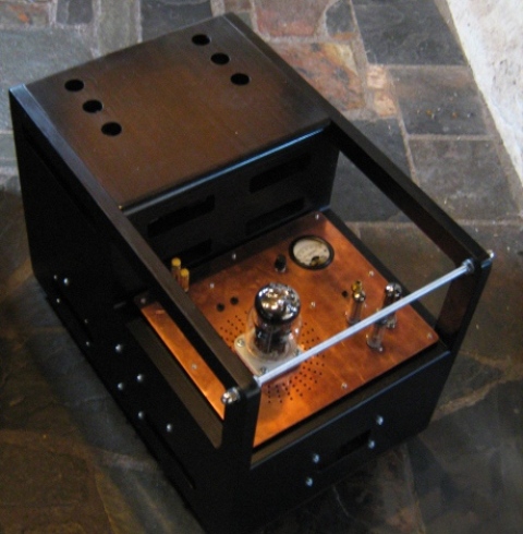
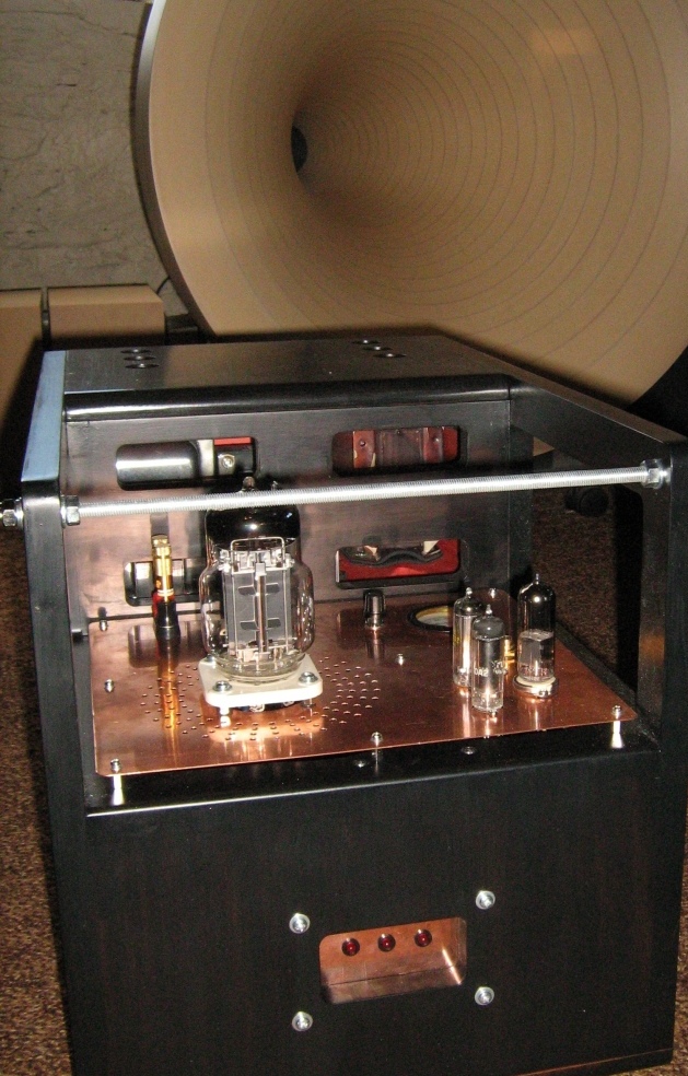
Here are a couple of pictures below. The chassis is 18mm mdf and the copper plate is cut from 0.7mm roofing/cladding copper sheets. Nothing too heavy attached the on copper plates and it seems to be ok. No fan for cooling, so lots of holes cut in the mdf for ventilation, so far so good for heat dissipation.
"BTW, Milq topology allows to do some crazy thighs, for instance do not use positive bays… I will tell you later on about it if you have interest…."
It will be good to hear about the "crazy thighs" but no hurry, as I will play around with the amp as is first...
Best Regards,
Charles
|
|
|
|
Posted by Romy the Cat on
10-25-2007
|
Charles,
you would not need a fan for a single channel full-range Melquiades. One 6C33C, and particularly in the way how you mount it, will not overhear this chassis. I very much like how you separated the amp section from PS and from the entire chassis. You might use the shock- absorbing stand-offs to hold the cupper plate. Also, the very major benefit is that you might easily modify this amp, changing the output tube or the layout of the parts on the copper plate – you juts replace the copper plate – very cool indeed. BTW, the McMaster-Carr has the threaded rods that you use in black color.
Charles, can I put your post into you’re a separate thread dedicated to your project, in case you would like to update it with your this thoughts about the sound of this thing?
Rgs, Romy the Cat
|
|
|
|
Posted by Romy the Cat on
01-29-2008
|
Charles, did you finish your second amp? How the who project worked out for you? Care to share any thoughts about the Milq sound?
The caT
|
|
|
|
Posted by Romy the Cat on
09-18-2008
|
| from email wrote: | | …. I have the valves etc. for the Melquiades but have not built it yet. I have begun thinking about the preamplification stage. Right now it is just purely passive. Is this not the optimal input for the Melquiades? |
|
Actually if you are trying to make a full-range Milq then the amps has none of the specific requirements for preamps, cable to drive, driving impedance, itc… I mean it might be important but a full-range Milq has no different behavior from this perspective than any other amps. It becomes very important and critical in case you go DSET and use filters to separate channels in the amp’s import. However, from this perspective Milq is also no different than any other amps. So, I would not impose any specific demand to preamplification stage to drive Milq. I am not a huge fun of passive preamps but the Milq’s design specific has nothing to do with this prejudges of mine…
The Cat
|
|
|
|
Posted by decoud on
02-01-2009
|
|
fiogf49gjkf0d Hi Romy,
I am building a modularizable version of the Melquiades (i.e. it is full range, but one can add more channels to it) and therefore wish to have the power supply in a separate enclosure. This raises two questions:
1. From what you say, points M and L in the circuit need to be in the main enclosure, but should everything upstream be in the power supply case?
2. Do you use something like a http://www.socapex.com/ to link the power between the two, or do you run separate cables for each line?
Regards,
d
|
|
|
|
Posted by Romy the Cat on
02-01-2009
|
|
fiogf49gjkf0d Yes, the last cap of power supply much be on the side of load as it shell have a short path to ground. Without it you will have “less bass”, more crosstalk in case it is a stereo amp with single PS and a few other negative things.
With cables is more complicated and you need to do some thinking: what you need and how you need it and what you might need in future if you are planning this amp to grow. I think if you are planning to add one or more channels then you might allow in the cable to have a couple more wires, who know, you might need other voltage in there. I do not know what would be the best practice all together I might just say what I have done.
I decided to separate filament and none-filament cable between PS and the Amp because the filaments are AC and other voltages are DC and I did not want the AC and DC run in a same cables, even to separate them by shilding. So, I have filament cables made that had 6 wires: two parallel runs for 6.3V, two parallel runs for 12.6V and two parallel runs for ground. Each wire is 15A – as you see it is a huge overbuild, you will understand why in a minute. For high voltage cable I have made a 22 wires cable. It sounds too many but do not forget that my cable care 6 wires for indication what each time delay relay goes off and the service voltages. All auxiliary voltages are not referenced to ground of the amp. Milq is single-ended with signal flows through ground and I did not what to contaminate the ground with return path from fans or LEDs. You also need to consider the fact that your PS and Amp might be disconnected while the caps care the charge so, you do not want any males cable sticking out of chassis. You might use mild bleeders to discharge the PS caps or to active the bleeders what the main relay turn the amp off.
I do not know how about you but for me to fight with those connectors was a pain in ass. So, I outsourced everything. I found a local company, similar to what you found. In my case it was Positronic Industries and they had Front Runner Series Circular Connectors, I am sure you will find somebody local. So, I got their catalog, met this rep and wrote a specification for the cables I need. Since I completely outsourced the cables and the connectors making I wrote a truly over then necessary offensive specification. It was expense (around $800 for everything) but they built all males, females and cables that I needed for the projects and I did not burn my fingers…
Rgs, Romy
|
|
|
|
Posted by decoud on
02-01-2009
|
|
fiogf49gjkf0d Very many thanks, Romy, the idea of someone else's doing it does appeal. I shall split the AC and DC in any case as you suggest.
|
|
|
|
Posted by Romy the Cat on
03-10-2009
|
|
fiogf49gjkf0d Here is another Milq amp looks like was built and it appears to be in Thailand. I do not read Tai and do not know anybody who doe but I am interesting what they discover while they build and after they did.
http://www.kaponk.com/node/648
The Cat
|
|
|
|
Posted by drdna on
03-11-2009
|
|
fiogf49gjkf0d | Romy the Cat wrote: | | Here is another Milq amp looks like was built and it appears to be in Thailand. I do not read Tai and do not know anybody who doe but I am interesting what they discover while they build and after they did. |
|
I could not understand the whole thing, but they do describe the sound as soft and sweet and say it is very lifelike.
Adrian
|
|
|
|
Posted by jp on
03-11-2009
|
|
fiogf49gjkf0d I could see why he says its "sweet", but in my experience its neutral, if not brutally honest.
|
|
|
|
Posted by Dominik on
05-23-2009
|
|
fiogf49gjkf0d Hi,
I try to find some set amplifier for my system, with one is not horn system
(in futhure it will by)
right now It is:
Open baffle:
Rall 5khz-30khz
lowther pm5 1khz-5khz
altec biflex lowpass at around 1-2 KHz No Hipass
AK151 in infinite baffle Lopass at 250 Hz
I am not specialist in dyi, but i have friend who can build amplifier
for me.
So, is Melquiades amp will by work for me? theoretically of course.
My budget is 4000$
oh, sorry for my english
Best
D.
|
|
|
|
Posted by Romy the Cat on
05-23-2009
|
|
fiogf49gjkf0d
Dominik,
It hard to say what would “work” for you. I usually do not advised what to do in term of the “obtaining efforts” I am not in business to sell the Melquiades idea. Let your friend who can build amplifiers examine Milq or perhaps to bald a prototype and to give you an advise, since he is your friend and he knows your objectives.
Rgs, Romy
|
|
|
|
Posted by Dominik on
05-25-2009
|
|
fiogf49gjkf0d Hi Romy,
My friend, is not a amplifier builder, he is working in sony service. He told me that it is no proplem for him
to build amp from scheme.
BUT, yesterday I look closer to Melquiades (help)threads on this forum (You did a good job)
And I decide to try build amp by myself, step by step. Maybe I will learn something.
This would by good experience for me.
I will start at order parts from tribute:
2x 350mA amorphous output transformer Is there any parts with one I can order frome tribute?
I promise that my next post will by grammar correct. My wife know english better then me.
Best regards
Dominik
|
|