|
Posted by anthony on
05-25-2015
|
|
fiogf49gjkf0d
Hi Romy,
I am planning my own DSET build. I have based my speakers on your Macondo and
am busy turning MDF horns in my spare time.
Once that is over I will move onto amplifiers. I plan to build a fullrange Melquiades for a
friend and then if that works out the DSET 6 or 7 channel version for myself.
Of course I have read the threads and am reasonably familiar
with the evolution of DSET Melquiades in the context of your system but there
are still a few questions. The question
at the front of my mind is the following hypothetical:
“How would you proceed with another DSET build knowing
what you know now?”
If you are willing I would like to work through this in
stages. This is a project that will
evolve with time as I build the speakers and move them into the new room. Initially there will be 5 Channels:
Raal Lazy Ribbon - Direct Tube
Drive
S2 into 400Hz tractrix
S2 into 250Hz tractrix
Fane 8M into 115Hz tractrix
Scanspeak 25W/8565-00 towers – 8 drivers each
Then, if the results are satisfactory and the final position
of the speakers in the room permits I will experiment with:
K15/40 Midbass Horn
Injection Channel
A very familiar system to you indeed, and I hope you don’t
mind me using it as my starting point. I
don’t want to spend a decade or two trying to develop a satisfying horn system
from scratch so I am using your documented experiences to make a strong start so
that with any luck and a measure of persistence my system is matured within a
couple of years and I can let the whole diy thing pass for other endeavours.
So, to start, I am unsure of a few things regarding the
operation of your amps.
-
Bias adjustment in the first stages. Looking at the final 6 Channel circuit
diagram the bias for Channels A, B and C are all fixed and non-adjustable. How do you manage the varying gain of the
6E5P tubes?
-
Gain structure.
What is the output from your pre-amp?
Mine is 1.5V RMS and 33 Ohm. I am
trying to get an idea about my required size for the 30K input resistor.
-
ULF through the Scanspeak line array. My calcs are that at 15W, the SPL at the
listening chair would be about 98dB at 20Hz, and much higher at 100Hz. This is loud enough for sure, but in your
experience is the 6C33C/Scanspeak combination good near the amplifiers maximum power?
Regards,
Anthony
|
|
|
|
Posted by Romy the Cat on
05-26-2015
|
|
fiogf49gjkf0d
 anthony wrote: anthony wrote: | | I plan to
build a fullrange Melquiades for a friend and then if that works out the DSET 6
or 7 channel version for myself. |
|
That is very good approach in my view. The
problem is in this approach that you have to have high sensitively speakers
that you would be able to use with that test full-range Milq. The behavior of
the Full range Milq win this other speaker might be not the same as it would be
with Milq. So, generally I would suggest
to have a Milq (or any other amp the you might like) to drive your particular acoustic
system with all passive filtration and spend at least 6 month to feel
comfortable in this configuration and to figure out your crossover strategy. (Or
to develop new listening objectives and consequential frustrations). Then you
can slowly to do DSET and line filtration.
| anthony wrote: | If you
are willing I would like to work through this in stages. This is a
project that will evolve with time as I build the speakers and move them into
the new room. Initially there will be 5 Channels:
Raal Lazy Ribbon - Direct Tube Drive
S2 into 400Hz tractrix
S2 into 250Hz tractrix
Fane 8M into 115Hz tractrix
Scanspeak 25W/8565-00 towers – 8 drivers each |
|
Naturally I “endorse” this configuration and I
think it might do very well. My only concern is that I feel that Raal Lazy
Ribbon are a bit too wide and too midrangy for use above 12K. The standard Raal
Lazy Ribbon drop 10dB at 6K that is not bad but if you made Alex to make the
ribbon twice more narrow then it will have steeper drop and you have a bit more
“punchier” HF with the lower filter order.
The standard Raal Lazy Ribbon as I understand are meant to be used in
two-3 way acoustic system where tweeter is crossed at 2.5-3.5K, so you would
need to run 3-rd or 4th order to get the result you want. BTW, I
very much might be wrong about it but I do think that the narrower ribbon would
be beneficial. Does it worth to pay to Alex extra for a custom job and to be able
to get “some” improvement? I do not have the answer to this question.
| anthony wrote: | | Bias adjustment in the first
stages. Looking at the final 6 Channel circuit diagram the bias for
Channels A, B and C are all fixed and non-adjustable. How do you manage
the varying gain of the 6E5P tubes? |
|
Yeas, there is no bias adjustment
in this driver stage nether I see a need to do it. You need to adjust bias if it
going away and in some other occasions but in this amp it is not necessary. The amp is set to get 200V on the driver stage
and it would mean approximately 4.3V in grid. Yes, some of the tubes have a few
DB leas or more gain but you do not change “gain” by setting bias. If you have
on place 190V or 210V it truly goes not make any difference. Keep neat 200V on
place and near 15K load and it would be fine. Saying it I would like to note that
nothing shall prevent you to add your own bias adjustment if you feel so. Just be informed that any
dealing with bias line is supper affective to sound, in fact ever more then
dealing with grid in my mind. You might
gain some questionable benefit by having bias fine-dialed but you would need to
put a trimmer in the bias line. Well, I find it is to be at least debatable…
| anthony wrote: | | Gain structure. What
is the output from your pre-amp? Mine is 1.5V RMS and 33 Ohm. I am
trying to get an idea about my required size for the 30K input resistor. |
|
My pream has no gain. My
frontend have high output and can swing I believe 3.5V. I think Bidat at 0dB
digital can push 5V but this would send the Milq grid to plate currents and you
do not want to be there with indirect heating. You can calculate the gain of the
amp. The driver has average of 33dB, +- a few DB. The output stage has I believe
3-4times. Then you need to subtract whatever you OPT consumes. You will not
have a high gain with this amp as it is two stager. If you have a Macondo-like
configuration and very large room (let sat over 800-1000 sq foot) and low
output frond end and no active preamp then you will feel that you have not enough
volume sometime. The whole beauty of Milg
that you have let say 4V in the input and to have the am on A1 you might run a wide
range of the frond end, including high output. The 30K input resistor is kind of less relevant
in Milq DSET as the input impedance of other channels will screw all input impedance
picture.
| anthony wrote: | | ULF through the
Scanspeak line array. My calcs are that at 15W, the SPL at the listening
chair would be about 98dB at 20Hz, and much higher at 100Hz. This is loud
enough for sure, but in your experience is the 6C33C/Scanspeak combination good
near the amplifiers maximum
power? |
|
You will be able to drive Scanspeak
line array from Milq ONLY in case you have VERY small room, you are very lucky
(as I was a few years back where the arrays were at active location of the
room) and if it were not a full range but 18-22W LF only amp. Otherwise I would
go for a different amp. It need o be said that it is very hard to prognosticate
anything,
|
|
|
|
Posted by anthony on
05-26-2015
|
|
fiogf49gjkf0d | Romy the Cat wrote: |
That is very good approach in my view. The
problem is in this approach that you have to have high sensitively speakers
that you would be able to use with that test full-range Milq. The behavior of
the Full range Milq win this other speaker might be not the same as it would be
with Milq. So, generally I would suggest
to have a Milq (or any other amp the you might like) to drive your particular acoustic
system with all passive filtration and spend at least 6 month to feel
comfortable in this configuration and to figure out your crossover strategy. (Or
to develop new listening objectives and consequential frustrations). Then you
can slowly to do DSET and line filtration. |
|
I will have the fullrange Milq for a few months after it is built, so I had better be quick getting the system in some sort of shape in that time.
| Romy the Cat wrote: | | My only concern is that I feel that Raal Lazy
Ribbon are a bit too wide and too midrangy for use above 12K. The standard Raal
Lazy Ribbon drop 10dB at 6K that is not bad but if you made Alex to make the
ribbon twice more narrow then it will have steeper drop and you have a bit more
“punchier” HF with the lower filter order.
The standard Raal Lazy Ribbon as I understand are meant to be used in
two-3 way acoustic system where tweeter is crossed at 2.5-3.5K, so you would
need to run 3-rd or 4th order to get the result you want. BTW, I
very much might be wrong about it but I do think that the narrower ribbon would
be beneficial. Does it worth to pay to Alex extra for a custom job and to be able
to get “some” improvement? I do not have the answer to this question. |
|
I have tried to contact Alex a couple of times in the past six months with something similar to your suggestion in mind. Both times he did not respond to my email so I figured that either I was too small a fish or that he was too busy. Seeing no better HF option, I have recently ordered the Lazy Ribbons and I doubt that Raal would have started building them yet, but I have contacted the distributor in my country this morning to see if he is able to prompt Alex into a conversation with me about this. We will see how it goes I suppose. I certainly would prefer a ribbon that is dedicated to HF, but if I can't talk to the man I can't get anything special.
| Romy the Cat wrote: | | Yeas, there is no bias adjustment
in this driver stage nether I see a need to do it. You need to adjust bias if it
going away and in some other occasions but in this amp it is not necessary. The amp is set to get 200V on the driver stage
and it would mean approximately 4.3V in grid. Yes, some of the tubes have a few
DB leas or more gain but you do not change “gain” by setting bias. If you have
on place 190V or 210V it truly goes not make any difference. Keep neat 200V on
place and near 15K load and it would be fine. Saying it I would like to note that
nothing shall prevent you to add your own bias adjustment if you feel so. Just be informed that any
dealing with bias line is supper affective to sound, in fact ever more then
dealing with grid in my mind. You might
gain some questionable benefit by having bias fine-dialed but you would need to
put a trimmer in the bias line. Well, I find it is to be at least debatable… |
|
Ok, thanks for this information. I will follow your lead in this regard.
| Romy the Cat wrote: | My pream has no gain. My
frontend have high output and can swing I believe 3.5V. I think Bidat at 0dB
digital can push 5V but this would send the Milq grid to plate currents and you
do not want to be there with indirect heating. You can calculate the gain of the
amp. The driver has average of 33dB, +- a few DB. The output stage has I believe
3-4times. Then you need to subtract whatever you OPT consumes. You will not
have a high gain with this amp as it is two stager. If you have a Macondo-like
configuration and very large room (let sat over 800-1000 sq foot) and low
output frond end and no active preamp then you will feel that you have not enough
volume sometime. The whole beauty of Milg
that you have let say 4V in the input and to have the am on A1 you might run a wide
range of the frond end, including high output. The 30K input resistor is kind of less relevant
in Milq DSET as the input impedance of other channels will screw all input impedance
picture.
|
|
I have talked to a fellow that has built the fullrange Milq and he has had issues with Milq gain in his system and had to dial up the gain from his preamp, which is why I asked the question here. Looks like I may need more than 1.5V SE from my dac if your sources have at least 3.5V and your gain structure is well thought out. My dac will give 2.7V balanced so perhaps I will need to look at a balanced input to the Milq.
| Romy the Cat wrote: | | You will be able to drive Scanspeak
line array from Milq ONLY in case you have VERY small room, you are very lucky
(as I was a few years back where the arrays were at active location of the
room) and if it were not a full range but 18-22W LF only amp. Otherwise I would
go for a different amp. It need o be said that it is very hard to prognosticate
anything, |
|
My room is 285 sq ft (6.08m x 4.35m) with a vaulted ceiling (with the peak running along the long axis of the room). It will be interesting to see where the horn stack ends up in the room and also where the bass array will be positioned. I am not sure if this qualifies as a very small room, but it certainly is not large.
|
|
|
|
Posted by Romy the Cat on
05-27-2015
|
|
fiogf49gjkf0d Make the full-range and then you will see where you are.
Still, I feel that for MF channels it is beneficial for do with a good DHT output
stage instead of 6C33C and perhaps it is a good idea to use DHT driver as well.
So, when you strategy your 5ch DSET do consider that you might want to do non-standard
Milq for MF. The Lazy Ribbon vs narrow Lazy Ribbon… that is not a big
deal. I would not spend too much effort to find Alex or whoever it might be.
You might even chose to go for another tweeter if you would like, like some
kind of exotic Japanese of not the contemporary cancroid type. You cannot make the judgment of what you need
as you do not know what kind MF amp will be driving your S2 and consequentially
you do not know what tweeter will “work” for you. Remember, you do not chose
the tweeter YOU like but rather you chose the tweeter that your MF channel
loves. So, I would advise do not worry about the tweeter and build the system without
it. Yes, you shall leave a room for it on your frame and you shall dedicate an
amp to it but do not lock on the amp topology at this point as you do not know
if you will be driving 16R or 0.0001R. About the amp gain – it is what it is. I
do not think that 2.7V balanced will help you as converting it to single ended
you will be losing the dBs. In realty I do not know what output voltages I
have. I do know that with 0.5V I have a “normal” sound in my room that some
people would consider too load. I think that friend of yours who has Milq sound
too soft has ether too low efficiency of the acoustic system or too large room.
In your case, if you have Milq driving the line away of 8 25W/8565-00 towers
drivers in the room of near 300 sq and tall ceiling I would predict that you
will be in a "dangers zone" and will be running out of gain.
Rgs, Romy the Cat
|
|
|
|
Posted by anthony on
05-27-2015
|
|
fiogf49gjkf0d | Romy the Cat wrote: | | Make the full-range and then you will see where you are.
Still, I feel that for MF channels it is beneficial for do with a good DHT output
stage instead of 6C33C and perhaps it is a good idea to use DHT driver as well.
So, when you strategy your 5ch DSET do consider that you might want to do non-standard
Milq for MF. |
|
My interest is mainly in the 10Y/801A/VT25 tubes on one hand and the 45 on the other hand. The YO186 also interests me a lot especially after reading your impressions of it in your circuit and system, but it is a very difficult tube to get a hold of and is quite expensive. The 10Y etc. seem relatively reasonably priced and quite available, however I don't have a ready-made circuit or even knowledge of how they work with Macondo, so I am tempted to just follow your DHT lead with the 6E6P and DHT MF, especially considering that I don't want to be testing/developing amplifiers for much longer than I have to even if I may end up with a better result going the longer route.
My primary concern about a DHT driver is the low gain of those tubes (10Y is about 8x compared to 6E5P of 32x) and having to use an input transformer to improve gain and its effect on the crossover for MF.
| Romy the Cat wrote: | In your case, if you have Milq driving the line away of 8 25W/8565-00 towers
drivers in the room of near 300 sq and tall ceiling I would predict that you
will be in a "dangers zone" and will be running out of gain.
|
|
I thought I might be pushing the limit. Do you think it would be possible to increase gain by using an input transformer on the DSET ULF channel to boost signal level? I am not sure how this would mess with the low-pass filter.
Otherwise I could add a decent SS amp or maybe even push-pull 6C33C.
Regards,
Anthony
|
|
|
|
|
|
|
Posted by anthony on
05-28-2015
|
|
fiogf49gjkf0d Romy, thank-you for your help so far. Unfortunately I now have some more hopefully simple questions regarding the "pre-final" schematic from your "6 Channel
Melquiades" thread (see below). 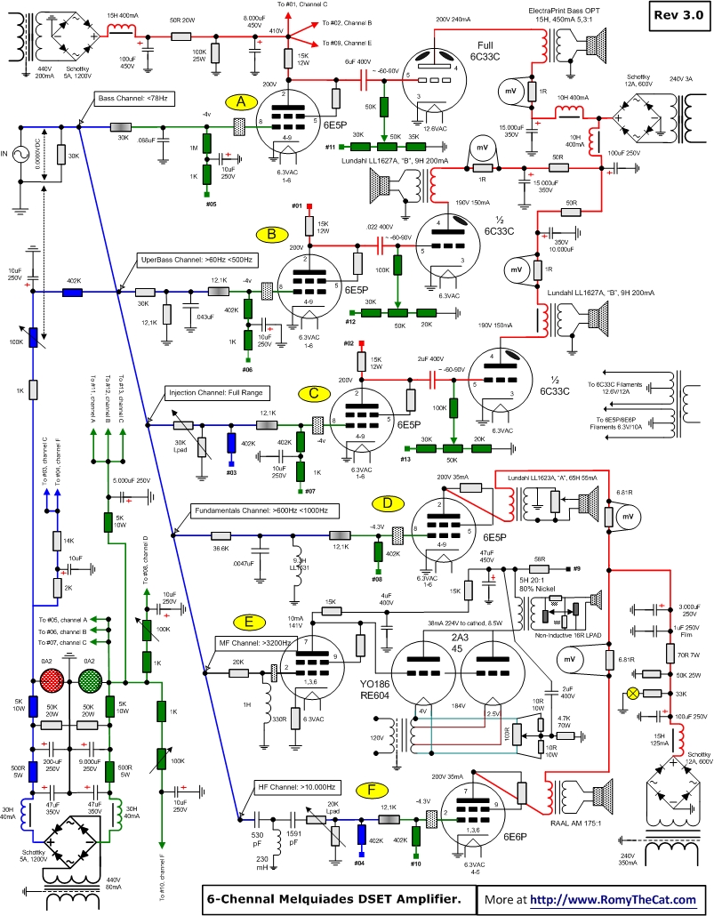
1.
Do you have a “final version” of the
schematic anywhere?
2.
6E5P/6E6P resistor between plate and
grid. Is this resistor influential to
sound? I notice that at one stage you
used a “high-quality” S102 resistor here but later on you are not necessarily
using them.
3.
What is the resistor in the
Fundamentals Channel between the OPT and the S2? Apart from this resistor you run the S2 without any components between it and the OPT.
4.
LPad for MF S2. Are you still running the LPad between the
OPT and S2? I assume that the four
resistors shown in the schematic at that position signify the LPad and not something else.
5.
Yellow circle with cross. On the schematic at the lower-right side
there is a yellow circle with a cross next to a 33K resistor. I am not familiar with this annotation…could
you please tell me what it is?
6.
Two sets of gas tubes. Have you considered more than one set of bias,
say one for LF and one for HF? Do you think
it could have any positive or negative effect?
I have no idea.
7.
mV Meters on B+. Is their only purpose to check the plate
voltage for the individual output stages?
Would you consider leaving them out?
8.
Do you use an hour meter to monitor
tube life? If so I imagine that it would
be installed straight after the power switch. Is this
true?
I apologise for the bombardment.
Regards,
Anthony
|
|
|
|
Posted by Romy the Cat on
05-29-2015
|
|
fiogf49gjkf0d
| anthony wrote: | | Do you have a
“final version” of the schematic anywhere? |
|
I think that the one you
have might be recognized as final. The Rev2 was without DHT in MF and Rev3 was
with it. I did not do anything else with the amp after that. The reality is
that 5-6 or any “n” number of DSET are just a parallel implementation of the
same amp with only biasing shared across all amps. The fact the biasing acts as
filtration, loading and voltage divider at the same time make it somehow complex
and confusing.
| anthony wrote: | | 6E5P/6E6P
resistor between plate and grid. Is this resistor influential to
sound? I notice that at one stage you used a “high-quality” S102 resistor
here but later on you are not necessarily using them. |
|
Well, the purpose
of this resistor just to rise a potential of one screen over another. You can
use the S102 thought and it will not hurt as they are phenomenal resistors. I did them and I did the CMF55 and they both
were fine. Did you heard any difference between Dales and S102 in the screen
lifter? I honestly did not test them ONLY in this application.
| anthony wrote: | | Is the resistor
in the Fundamentals Channel between the OPT and the S2? Apart from this
resistor you run the S2 without any components between it and the OPT. |
|
.
Actually it is not a resistor connected to OTP, look closer. This is a regular screen
lifter, like in your question above, it is juts drown perhaps not so friendly but as you see the red line
goes from plate and directly to OPT.
| anthony wrote: | | .LPad for MF
S2. Are you still running the LPad between the OPT and S2? I assume
that the four resistors shown in the schematic at that position signify the
LPad and not something else. |
|
This is complicated question and I did
cover it while I was dealing with it. I need to attenuate MF for ~2dB. In addition
the S2 driver if it driver very “clean” has some very very minor metallic fanzines
atop. My YO186 is very not neutral, it is sort of anti 10Y or anti type 45 tube.
As the resole I have very interesting and I would say “simulated” MF but with
very very very mild harshness atop. There are many way to deal with the mild harshness
atop and one of the way is to put a very mild low pass filter before S2. It should
be super low indictor that would hit the driver at 60-80Kz, wish at its low knee
will hold S2 a bit at over 20Kz. Any indictors I trues combined with voltage dividers
were detectable. What worked the best were not voltage dividers but the regular
ugly wired attenuators, some sort of miniature rheostats. The problem is that they are hugely inductive,
much more than necessary to deal with S2 fanzines. So, I found a solution to bypass
the wired attenuators with two S102 resistors, kind of building a second divider
with S102 and run it along with the wired one. The S102 have ultra-low inductance
and if you connect the indictors in parallel then the summazing indictors will
be less than the lowers one. As the result I have literally a problem free attenuation
on my MF that at the same time do take care of my S2 “fanzines”.
| anthony wrote: | | Yellow circle
with cross. On the schematic at the lower-right side there is a yellow
circle with a cross next to a 33K resistor. I am not familiar with this
annotation…could you please tell me what it is? |
|
Well, from the annotation
perspective it would looks like it was a lamp. I do not remember what it is and
it looks like lamp but why the hell I took voltage to some kind of light emitting
diode from B+ if I have a dedicated service 12V voltage running thought out all
amp? I do not remember the answer.
| anthony wrote: | | Two sets of gas
tubes. Have you considered more than one set of bias, say one for LF and
one for HF? Do you think it could have any positive or negative
effect? I have no idea. |
|
It is possible to use as many gas tubes
you wish, they are juts supple of negative bias. In my version I used one foe
all channels. I do not know about sonic impact it has compare with own
dedicated gas tube. I think own dedicated gas tube would shall be better but I made
no practical experiments with it.
| anthony wrote: | | mV Meters on
B+. Is their only purpose to check the plate voltage for the individual
output stages? Would you consider leaving them out? |
|
Sure, the mV Meters do not need to be there. You need
to have 1R resistors and to access to
left and right of them, the service points would be fine, and you then can you regular
tester to measure it. I fine it is fine in a single full range but in case you
have many 6C33C to deal with at the same time then it is very convenient to
have the permanent meter.
| anthony wrote: | | Do you use an
hour meter to monitor tube life? If so I imagine that it would be
installed straight after the power switch. Is this true? |
|
You can
install the hour meter anywhere you wish. If it is low voltage devise then I
would put it in service voltage. I was thinking to do it but for some reasons I
did not make it. Now I feel that I do not miss it and I feel that it rather was
my wishful thinking devise then the actually helpful tool. If you have multiple
6C33C for multiple channels then they
will die with different tempo. Do you want to keep a chronometer for
each of them? It is not to mention that knowing the tube hours is not necessary
allow to know if the tube need to be replaced as some of them dies after 500 hours
and some of them work for years and demonstrate no sign of aging.
|
|
|
|
Posted by anthony on
05-29-2015
|
|
fiogf49gjkf0d | Romy the Cat wrote: |
| anthony wrote: | | Is the resistor
in the Fundamentals Channel between the OPT and the S2? Apart from this
resistor you run the S2 without any components between it and the OPT. |
|
.
Actually it is not a resistor connected to OTP, look closer. This is a regular screen
lifter, like in your question above, it is juts drown perhaps not so friendly but as you see the red line
goes from plate and directly to OPT.
|
|
The resistor between the transducer and OPT is the one that I am not sure of. Do you still have a resistor before the S2?
|
|
|
|
Posted by Romy the Cat on
05-31-2015
|
|
fiogf49gjkf0d I do not nave, neither I see in the schematic, a resistor
but rather an Lpad shunted with two resistors, exactly how I described above.
|
|
|
|
Posted by anthony on
06-01-2015
|
|
fiogf49gjkf0d Sorry Romy, I was not clear enough, but the resistor that I am questioning is in the Fundamentals Channel (not the MF Channel as I believe you referred to in your previous post) between the OPT and the S2.
|
|
|
|
Posted by Romy the Cat on
06-01-2015
|
|
fiogf49gjkf0d | anthony wrote: | | Sorry Romy, I was not clear enough, but the resistor
that I am questioning is in the Fundamentals Channel (not the MF Channel as I
believe you referred to in your previous post) between the OPT and the
S2. |
|
Ah, the Fundamentals Channel,
that is totally different story. I have a regular highly inductive 16R L-pad in
there, just at the speaker level. The upper knee of the Fundamentals Channel is
second order 1000Hz at line-level and you do want to drive as much as possible
HF out of this channel. The additional inductive roll off at top only helps to
this Channel, even I do not think that it is truly auditable.
|
|
|
|
Posted by anthony on
06-02-2015
|
|
fiogf49gjkf0d Thanks Romy.
I have secured a couple of pair of YO186 and some 1940's Sylvania 45's to play with. I wish the YO186 were easier to come by but I think that I now have enough for me to get a very good idea of the capabilities of the tube and circuit, and how they will suit my objectives.
Still, I am thinking about the 10Y/801A/VT25/VT62. Romy, I understand that to bring the 10Y into Melquides I would need 7.5V for the filaments and about 400V for the plate. Plate resistance is higher in the 10's, 5k compared to about 1.2k-1.6k for YO186/45, and I am not sure how this would affect operation of the Milq circuit particularly interstage coupling. Reading up I have noticed that some guys prefer much more primary impedance in the OPT than the 10k specified in the 10Y datasheet, up to 16k in fact. Of course this is in the context of a full-range implementation but I notice that the David Slagle OPT that you use for MF has a 9k primary impedance (if my memory serves me right), which is getting near there already.
I have noticed that you have written about your interest in the 10Y, and I am for sure no circuit designer, but given your experience with Milq perhaps you could share some of your thoughts about the viability of putting this tube into the Milq for MF. Compared to the 45, I am not sure what extra the 10Y would bring as far as sound is concerned (I can only go on "impressions" of other people with other systems using the tubes differently), but seeing as though I will be starting from scratch with my DSET I would be able to add the required voltages for 10Y upfront so long as it does not look too difficult to get the tube to work with 6E6P.
Regards,
Anthony
|
|
|
|
Posted by Romy the Cat on
06-02-2015
|
|
fiogf49gjkf0d | anthony wrote: | I have secured a couple of pair of YO186 and some
1940's Sylvania 45's to play with. I wish the YO186 were easier to come
by but I think that I now have enough for me to get a very good idea of the
capabilities of the tube and circuit, and how they will suit my objectives.
Still, I
am thinking about the 10Y/801A/VT25/VT62. Romy, I understand that to
bring the 10Y into Melquides I would need 7.5V for the filaments and about 400V
for the plate. Plate resistance is higher in the 10's, 5k compared to
about 1.2k-1.6k for YO186/45, and I am not sure how this would affect operation
of the Milq circuit particularly interstage coupling. Reading up I have
noticed that some guys prefer much more primary impedance in the OPT than the
10k specified in the 10Y datasheet, up to 16k in fact. Of course this is
in the context of a full-range implementation but I notice that the David
Slagle OPT that you use for MF has a 9k primary impedance (if my memory serves
me right), which is getting near there already.
I have
noticed that you have written about your interest in the 10Y, and I am for sure
no circuit designer, but given your experience with Milq perhaps you could
share some of your thoughts about the viability of putting this tube into the
Milq for MF. Compared to the 45, I am not sure what extra the 10Y would
bring as far as sound is concerned (I can only go on "impressions" of
other people with other systems using the tubes differently), but seeing as
though I will be starting from scratch with my DSET I would be able to add the
required voltages for 10Y upfront so long as it does not look too difficult to
get the tube to work with 6E6P. |
|
Well, the YO186 and Type 45
are in way the same tubes as they to a degree might use the same OPT and have
near the same operational points. You can make an amp with both tube sockets
and you will be able to plug in probably 80% of DHT out there. Wherever YO186 goes
you will be able to put PX4, RE604,
RE-614, LK460, 610 and other does of 4V tubes, that arguably the
best tube out there, In Type 45 socket
you will be able to plug any 45, 50, 2A3 and many other tubes. This will give
you incredible playground. Is it necessary? When I was building the amp and experimented
I would say that it was. As now I feel that that it was not necessary and sine
I found my winning configuration I do not take advantage of changing anything.
If you want to spread the amp to use 10Y/801A/VT25/VT62
then you would need another socket with another filament voltage, might higher
plate voltage and another transformer. Is it double? Of cause it does! However,
if I did it again then I would not do it in context of multi-channel amplifier
but rather I would make a maket amplifier able would test my ideas with it.
You see, the problem is that
the “best” MF amplifier for you will be NOT the best amplifier but rather the
best amp that would feet into the schema of your demands and the capacities of
the rest of your channels. It is VERY hard to estimate what would it be, not to
mention that your audio expectation might be a moving target and most likely will
be recompiled after the first revision of you project will be over.
I would not be advising you
about the use of 10Y as I do not have proven experience with this tube. My
short and environmentally not-kosher experiments with this tube did show great
potential but it was a bit wrong direction to me. The 10Y was super clean tube,
kind of aka Type 45 only even “cleaner”. I however was not looking for this cleanneness
in my MF but rather I was looking for a lot of distortion but very specific
type of distortion. The under-voltaged YO186 gave it to me, but I would never
accept that same under-voltaged sound for a good full-range amplifier.
|
|
|
|
Posted by anthony on
06-02-2015
|
|
fiogf49gjkf0d | Romy the Cat wrote: |
However,
if I did it again then I would not do it in context of multi-channel amplifier
but rather I would make a maket amplifier able would test my ideas with it. |
|
While I do like the idea of experimenting with MF sounds and then building just one DHT into the final Milq, I think that it may take me some time to decide between the YO186 and 45 types of sounds, especially as I tune a foreign to me system to my preferences.
| Romy the Cat wrote: | | You see, the problem is that
the “best” MF amplifier for you will be NOT the best amplifier but rather the
best amp that would feet into the schema of your demands and the capacities of
the rest of your channels. It is VERY hard to estimate what would it be, not to
mention that your audio expectation might be a moving target and most likely will
be recompiled after the first revision of you project will be over. |
|
Yes I am sure that you are correct about about the MF amplifier having to play properly with the other channels. I am also quite sure that my audio expectations will be to some extent a moving target when I start to listen and tune the channels and understand what they are capable of contributing. Hopefully I can make it all work to my satisfaction.
| Romy the Cat wrote: | | I would not be advising you
about the use of 10Y as I do not have proven experience with this tube. My
short and environmentally not-kosher experiments with this tube did show great
potential but it was a bit wrong direction to me. The 10Y was super clean tube,
kind of aka Type 45 only even “cleaner”. I however was not looking for this cleanneness
in my MF but rather I was looking for a lot of distortion but very specific
type of distortion. The under-voltaged YO186 gave it to me, but I would never
accept that same under-voltaged sound for a good full-range amplifier. |
|
I am often drawn to the super-clean sound which is largely why the 10Y interests me, but I have embarked on this Macondo/Melquiades project because I think that overall the system gives me many methods to get the sounds that I want. Although I do enjoy classical music, I do not limit myself to that genre alone plus I have two quite musical young children that will want to listen to all kinds of music as they grow up. If the YO186, or some other "distorting" tube manages to strike me as it has you, then I think that a "clean" tube may also still be in order as the kids explore other genres. So what I think I will do is build your MF channel as shown in the schematic, but leave room in the power supply to add a couple of more voltages so that if I feel the need down the track that I can go with the 10Y, or perhaps even a DHT driver, or both.
Thanks for your help so far Romy.
|
|
|
|
Posted by Romy the Cat on
06-03-2015
|
|
fiogf49gjkf0d | anthony wrote: | | I am often drawn to the
super-clean sound …. |
|
I do not think that use the term of “super-clean sound” in
the same way. Vienna Philharmonic does not have “super-clean sound” from
the perspective of most of contemporary orchestras. They have different fingering on
clarinets, different reeds on oboes, rotary trumpets, narrow trombones, valveless
horns and dozens other differences, some the part of design and some of the
part of usability. As the result the sound is very distinctively different very
far from “clean” but it has completely deferent meaning when colorations actually
do server a very positive purpose and that coloration do fort what we call
today Viennese Sound. It is very difficult to go for this level of sonic creativity
with audio but only after one does go there then the use of term of “super-clean
sound” with some kind “offence” connotation I find reasonable. I do think that until
you experiment with “non- cleanliness injections” (in one way or other) you truly do not use
the term of “super-clean sound” in the same way as I do.
|
|
|
|
Posted by anthony on
06-03-2015
|
|
fiogf49gjkf0d | Romy the Cat wrote: | | anthony wrote: | | I am often drawn to the
super-clean sound …. |
|
I do not think that use the term of “super-clean sound” in
the same way. Vienna Philharmonic does not have “super-clean sound” from
the perspective of most of contemporary orchestras. They have different fingering on
clarinets, different reeds on oboes, rotary trumpets, narrow trombones, valveless
horns and dozens other differences, some the part of design and some of the
part of usability. As the result the sound is very distinctively different very
far from “clean” but it has completely deferent meaning when colorations actually
do server a very positive purpose and that coloration do fort what we call
today Viennese Sound. |
|
I chastise my father from time to time because these days he often begins stories in the middle and leaves out the beginning where the context is set, and in my previous post I left out the context regarding "super-clean".
The way that I was using "super-clean" of course has caveats: I don't like it across the board for all (or probably most) of the music that I listen to; some modern music that is intentionally stripped of the harmonics during production actually seems to benefit from a "super-clean" or even "sterile" playback (think electronic music in particular, or modern R&B). I do listen to electronic music occasionally (throwback to my youth probably) and believe it or not much of it is quite well mastered and with all its tricks and quirks and hooks it does sound very good on a "super-clean" system. But then I listen to Mahler or Elgar or Jascha Heifetz and I yearn for a greater immersion in the colours and emotions of their works..."super clean" just does not work for me there.
| Romy the Cat wrote: | It is very difficult to go for this level of sonic creativity with audio but only after one does go there then the use of term of “super-clean sound” with some kind “offence” connotation I find reasonable. I do think that until you experiment with “non- cleanliness injections” (in one way or other) you truly do not use the term of “super-clean sound” in the same way as I do. |
|
Well, that, in a nutshell, is why I have chosen Macondo/Melquiades. My version of super-clean was only working on occasion for me, and it was generally under-whelming on much of the music I love, but without building speakers and amplifiers myself and experimenting/learning for a long, long time I could not see a viable way of getting just what I want. Hopefully Macondo/Milq will shorten the long, long time into just a long time, and I will end up with a system on which I can play any style of music to my satisfaction.
Regards,
Anthony
|
|
|
|
Posted by anthony on
06-03-2015
|
|
fiogf49gjkf0d So, looking at the schematic below...
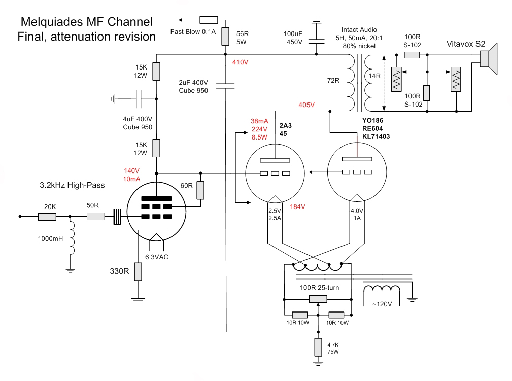
...I have a few more questions
- 25 turn pot in the filament supply. For the life of me I can't source a 25 turn pot. The 10 turn Bourns 3590 is the closest I can find. Do I need to keep looking for a more sensitive pot or do you think 10 turn is manageable?
- The fuse. You show a fuse on this schematic (that traces back to the B+ supply) but omit it on the 6-Channel schematic that I linked to earlier in the thread. Do you use this fuse or have you removed it?
- HP Filter 50R. In the schematic above you use a 50R resistor leading into the 6E6P but omit it on the 6 Channel schematic. As far as I can tell it is not required for the high-pass RL filter so do you use the 50R or has it been removed?
- Changing valves. Could you please explain to me the process of changing valves, say from 45 to YO186? Please treat me as an imbecile in this regard. I am very interested in the process and think that it will help me better understand its use. If I were to guess I would say shut down the amps; remove 45; install YO186; turn on amps; adjust 100R pot to read ???? through the measuring points; press play. Or maybe it is simpler than that...in some photographs I notice a switch on the "DHT Island" but do not know what it is for.
|
|
|
|
Posted by Romy the Cat on
06-04-2015
|
|
fiogf49gjkf0d | anthony wrote: | | 25 turn
pot in the filament supply. For the life of me I can't source a 25 turn
pot. The 10 turn Bourns 3590 is the closest I can find. Do I need
to keep looking for a more sensitive pot or do you think 10 turn is manageable? |
|
Sure it is manageable. This is just pure the matter of comfort.
| anthony wrote: | | The fuse. You show a
fuse on this schematic (that traces back to the B+ supply) but omit it on the 6-Channel
schematic that I linked to earlier in the thread. Do you use this fuse or
have you removed it? |
|
Yes, I use 7.5A slow blow at the very entrance
of the 6-Channel schematic with the amp drown in cruse mode in mid of 4A.
The slow blow is critical as the amp will start
up and begin to saturate the chokes it will draw instantly over 3kW. The normal
consumption is 375W if I am not mistaken.
| anthony wrote: | | HP Filter
50R. In the schematic above you use a 50R resistor leading into the 6E6P
but omit it on the 6 Channel schematic. As far as I can tell it is not
required for the high-pass RL filter so do you use the 50R or has it been
removed? |
|
Well, the 6E6P is very fast tube and have tendency for microphonic
effect, in particularly while it I cold. It is a common practice to put a very small
resistor (50-100R) right before the grid entrance to stop any stray noised to
come to the grid and arouse the tube. This is call grid stopper. The ferrite
bids serve the same purpose. So, the grid stoppers with fast tube are not part
of semantics but rather a part of regular design hygiene and they are implied
with those type of tubes. On the 6 Channel schematic I just did not have space
to depict it but I still would use it in particularly if your wires from the
coil are too long as they act as antenna picking up all imaginable dirt in the
amp chasses.
| anthony wrote: | | Changing
valves. Could you please explain to me the process of changing valves,
say from 45 to YO186? Please treat me as an imbecile in this regard.
I am very interested in the process and think that it will help me better
understand its use. If I were to guess I would say shut down the amps;
remove 45; install YO186; turn on amps; adjust 100R pot to read ???? through
the measuring points; press play. Or maybe it is simpler than that...in
some photographs I notice a switch on the "DHT Island" but do not
know what it is for. |
|
Yes, that is exactly how you describe the process.
You adjust the 100R in order to kill the noise on the output. What I do is use
mili-voltmeter on the terminal of S2 and try to set the voltage in there under
3mV. I think anything above 20mV is auditable, Anything under 10mV is dead
silent. Another very important factor when you change the tube and try to compare
them is that they all will have slightly different gain. So here is what I do.
My tuner has 1kHz calibration tone, it is convenient and I do not need to bring
a generator or test CD).
1) Drive the
calibration tone and measure the AV at the speaker (I prefer to do it electrically not acoustically)
2) Follow
your procedures to replace the tubes
3) Drive the
calibration tone with the new tube and measure the SAME AV at the speaker. If
the AV not same then use the post OTP attenuator to make it the same.
There is some “kind” into it. Some tubes you do not mind to drive
louder (mostly dark tubes: PX25, RE604, YO186, 2A3 with
single plate for
instance) and some you would like to run softer (type 45, 30, 2A3 etc…).
You will end up with whatever you prefer eventually. Be advised that the output
of Fundamentals, HF and Insertion channels will greatly impact how you would
like to hear your MF.
|
|
|
|
Posted by anthony on
06-05-2015
|
|
fiogf49gjkf0d | Romy the Cat wrote: |  anthony wrote: anthony wrote: | | The fuse. You show a
fuse on this schematic (that traces back to the B+ supply) but omit it on the 6-Channel
schematic that I linked to earlier in the thread. Do you use this fuse or
have you removed it? |
|
Yes, I use 7.5A slow blow at the very entrance
of the 6-Channel schematic with the amp drown in cruse mode in mid of 4A.
The slow blow is critical as the amp will start
up and begin to saturate the chokes it will draw instantly over 3kW. The normal
consumption is 375W if I am not mistaken. |
|
Do you still use the fuse shown in the MF channel schematic linked above (not the 6 Channel schematic)?
Regarding the mains fuses I will have to recalculate them for the mains voltage where I am...they should roughly halve for 240v.
| Romy the Cat wrote: |
| anthony wrote: | | HP Filter
50R. In the schematic above you use a 50R resistor leading into the 6E6P
but omit it on the 6 Channel schematic. As far as I can tell it is not
required for the high-pass RL filter so do you use the 50R or has it been
removed? |
|
Well, the 6E6P is very fast tube and have tendency for microphonic
effect, in particularly while it I cold. It is a common practice to put a very small
resistor (50-100R) right before the grid entrance to stop any stray noised to
come to the grid and arouse the tube. This is call grid stopper. The ferrite
bids serve the same purpose. So, the grid stoppers with fast tube are not part
of semantics but rather a part of regular design hygiene and they are implied
with those type of tubes. On the 6 Channel schematic I just did not have space
to depict it but I still would use it in particularly if your wires from the
coil are too long as they act as antenna picking up all imaginable dirt in the
amp chasses. |
|
Well I would have missed that one...so thanks for that. These will be my first amplifier builds so I will probably miss those kinds of things. Can you think of any others that I will probably miss?
| Romy the Cat wrote: |
Yes, that is exactly how you describe the process.
You adjust the 100R in order to kill the noise on the output. What I do is use
mili-voltmeter on the terminal of S2 and try to set the voltage in there under
3mV. I think anything above 20mV is auditable, Anything under 10mV is dead
silent. Another very important factor when you change the tube and try to compare
them is that they all will have slightly different gain. So here is what I do.
My tuner has 1kHz calibration tone, it is convenient and I do not need to bring
a generator or test CD).
1) Drive the
calibration tone and measure the AV at the speaker (I prefer to do it electrically not acoustically)
2) Follow
your procedures to replace the tubes
3) Drive the
calibration tone with the new tube and measure the SAME AV at the speaker. If
the AV not same then use the post OTP attenuator to make it the same.
There is some “kind” into it. Some tubes you do not mind to drive
louder (mostly dark tubes: PX25, RE604, YO186, 2A3 with
single plate for
instance) and some you would like to run softer (type 45, 30, 2A3 etc…).
You will end up with whatever you prefer eventually. Be advised that the output
of Fundamentals, HF and Insertion channels will greatly impact how you would
like to hear your MF. |
|
Thanks Romy, but I don't know what you mean by AV in the text above. Do you mean dB?
One more question. The filament supply of the MF Channel has the hum management circuitry on the 4v secondary...do you also use an artificial centre tap on the 2.5v secondary? I just thought that it might be one of those "hygiene" things that you left off the schematic. Likewise for the filament supplies of the other channels.
Regards,
Anthony
|
|